Engineering a 3D Rendering Aluminum Facade From Wind Load to Shop Drawing
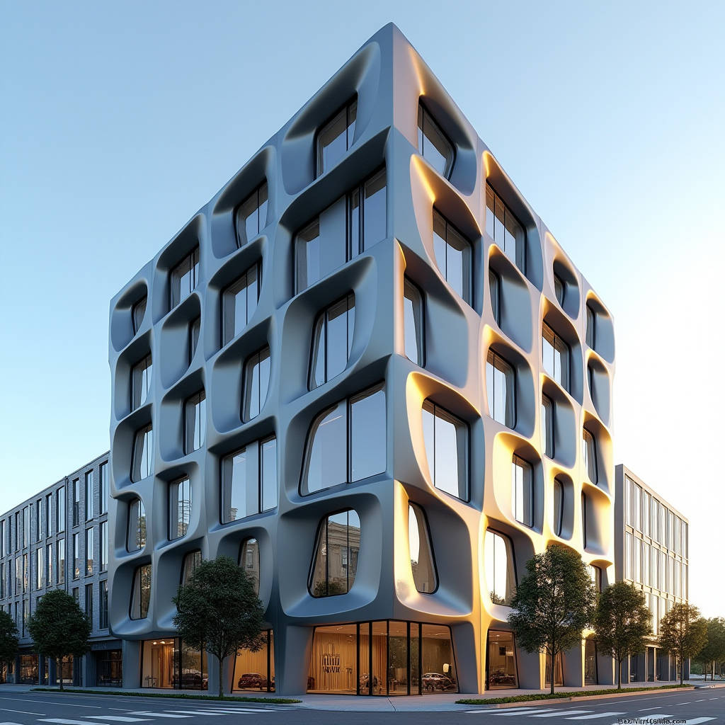
When a facade transitions from a flat extrusion to a sculpted, three-dimensional form, the entire risk profile of the project shifts. A 3D Rendering Aluminum Facade is not a visual novelty; it is a structural and financial decision that must be validated before a single sheet is ordered. The search results above confirm a growing market appetite for sculpted and laser-cut aluminum panels, yet most renderings stop at aesthetics. This article examines the engineering reality behind those renderings: how panel depth, wind load, fabrication tolerance, and coating performance interact, and why the render must be treated as a technical specification rather than a marketing image. We will walk through the load path, the fabrication constraints unique to solid aluminum sheets, and the cost implications that appear only when the model becomes a shop drawing.
From Render to Load Path
Every sculpted panel changes the wind load distribution across the facade. A flat 3.0 mm solid aluminum panel behaves like a simple plate under uniform pressure. Once you introduce a three-dimensional profile, the panel develops both membrane and bending stresses that a standard flat-panel calculation will not capture. The render software shows you the geometry; it will not tell you whether the stiffening ribs are sufficient.
For a 3D Rendering Aluminum Facade, the first engineering step is to extract the actual panel geometry from the model and run a finite element analysis. The AAMA 501.1 test method remains the accepted standard for verifying dynamic water penetration and structural performance of exterior wall systems, but it tests the assembled system, not the individual sculpted panel. You need both. The render gives you the shape; the FEA gives you the stress map.
Wind Load and Deflection Limits
Typical facade design uses a serviceability deflection limit of L/180 for the overall system and L/60 for individual panels, though many specifiers tighten this to L/90 for visible aluminum surfaces. A sculpted panel with a 50 mm depth will behave differently from a flat panel of the same thickness because the profile adds stiffness in one direction while leaving the other direction vulnerable. The render must therefore include the stiffening strategy, not just the cosmetic depth.
Consider a 1500 mm by 3000 mm panel in a 45 m building corner zone. The design wind pressure at that height can reach 2.8 to 3.5 kPa depending on local exposure. A flat 3.0 mm panel with adequate stiffeners handles this comfortably. The same panel with a deep sculpted profile may require intermediate vertical stiffeners every 600 mm, which changes the fabrication cost and the weight of the assembly.
Fabrication Constraints of Solid Aluminum
Solid aluminum cladding panels are produced from coils of 3003 or 5052 alloy, then cut, folded, and welded. The sculpted forms seen in modern renders are usually achieved through one of three methods: press braking, roll forming, or laser cutting. Each method imposes its own constraints on the geometry that the render must respect.
Press braking creates crisp, angular folds but struggles with continuous curves. Roll forming handles long, consistent profiles but requires a minimum run length to be economical. Laser cutting, as highlighted in the search results, allows intricate patterns and perforations but adds significant cost per square meter and creates stress concentrations that must be analyzed. A render that shows a complex doubly curved panel will likely require a multi-axis CNC process, which is a different cost bracket entirely.
| Forming Method | Min. Radius | Max. Practical Depth | Tooling Cost | Typical Use |
|---|---|---|---|---|
| Press Braking | 1.5–2.0 × t | 80–120 mm | Low–Medium | Angular sculpted panels, box ribs |
| Roll Forming | 3.0–4.0 × t | 60–100 mm | High (dies) | Long continuous profiles, louvers |
| Laser Cutting | 0.5 × t (kerf) | Flat or shallow | Per-piece | Perforated and patterned panels |
| CNC Stretch Forming | 200–500 mm | 150+ mm | Very High | Doubly curved architectural panels |
The fabrication tolerance for sculpted panels is tighter than for flat panels. A flat panel can absorb minor dimensional variation through the joint design. A sculpted panel that must align with its neighbors across a 10 mm open joint cannot tolerate more than ±1.5 mm in the profile depth, otherwise the shadow lines become inconsistent and the facade reads as defective. This tolerance directly affects the cost of the tooling and the scrap rate during production.
Coating Performance on Complex Geometry
The coating on a 3D Rendering Aluminum Facade receives more scrutiny than on a flat surface because the human eye detects color and gloss variation across angled surfaces. A 70% PVDF coating system, applied at 25 microns total film thickness, is the standard for architectural aluminum. On a sculpted panel, the coating must be applied after forming, which means the profile must be designed so that no surface is shielded from the spray gun.
Deep recesses and sharp internal corners are the failure points. Electrostatic spray application has difficulty reaching the inside of a 50 mm deep channel, leading to thin film at the bottom of the recess. The AAMA 2605 specification, the highest performance level for organic coatings, requires a minimum film thickness that must be verified at the most difficult-to-reach point, not just on the flat face. This is a common source of field failures that no render will reveal.
For coastal environments, the specifier should require a 70% PVDF resin system with a 2-coat or 3-coat build, and should verify that the coating supplier holds AAMA 2605 certification. The render should show the coating as a functional layer, not just a color. If the profile has internal surfaces that cannot be coated to spec, the design must be revised before fabrication.
Cost Drivers Hidden in the Render
The render shows a beautiful sculpted facade, but the cost model is built from the fabrication data. Several cost drivers appear only when the geometry is quantified. The first is material yield. A sculpted panel with a deep profile may require a larger blank size than the projected area, because the profile is formed from a flat sheet that is bent or stretched. This increases the material cost per square meter of facade area.
The second driver is the stiffening system. A 3.0 mm solid aluminum panel with a 600 mm stiffener spacing weighs roughly 8.1 kg per square meter for the sheet alone, plus the stiffeners and brackets. A sculpted panel that requires stiffeners at 400 mm spacing adds another 30 to 40 percent to the framing weight, which increases the cost of the substructure and the anchors.
The third driver is installation time. Sculpted panels are heavier and more difficult to handle than flat panels, and the alignment tolerance is tighter. A typical flat panel installation achieves 25 to 35 square meters per crew per day. A sculpted panel with complex geometry drops to 12 to 18 square meters per day, which directly increases the labor component of the facade cost.
Cost Comparison Table
| Facade Type | Panel Thickness | Material Cost (USD/m²) | Fabrication (USD/m²) | Installation (USD/m²) | Total (USD/m²) |
|---|---|---|---|---|---|
| Flat Solid Aluminum | 3.0 mm | 55–70 | 25–35 | 30–40 | 110–145 |
| Shallow Sculpted (20 mm) | 3.0 mm | 70–90 | 45–60 | 40–55 | 155–205 |
| Deep Sculpted (50 mm) | 3.0 mm | 90–120 | 70–95 | 55–75 | 215–290 |
| Laser-Cut Patterned | 3.0 mm | 85–110 | 110–160 | 50–70 | 245–340 |
These figures are order-of-magnitude estimates for a mid-rise project in a developed market and will vary with region, alloy, and coating specification. The pattern is clear: the visual depth of the render translates directly into a nonlinear cost increase. A 50 mm deep profile costs roughly double a flat panel, and a laser-cut pattern can approach triple.
Structural Testing and Certification
Before committing to a sculpted facade, the design team should require a mock-up test of the actual panel geometry. The AAMA 501.1 method covers dynamic water penetration and structural performance, but a sculpted panel also needs static air infiltration and water penetration testing per ASTM E283 and E331. These tests are performed on a full-scale mock-up, not on a render, and they catch the failures that appear only in real geometry.
The mock-up also validates the joint design. A sculpted panel with a 10 mm open joint must be tested for water penetration at the design wind pressure, because the joint geometry on a sculpted panel is more complex than on a flat panel. The gasket and drainage details that work on a flat facade often fail on a deep profile, and the fix is expensive after fabrication begins.
For the substructure, the specifier should reference the Aluminum Association's design manual for allowable stresses in 6063-T6 and 6061-T6 extrusions. The brackets and rails that support a sculpted panel are typically extruded aluminum, and their design must account for the eccentric loading created by the panel's depth. A flat panel loads the bracket in one plane; a sculpted panel adds a moment that the bracket must resist.
Specifying the Render Correctly
The most common failure in a 3D Rendering Aluminum Facade project is not structural; it is a mismatch between the render and the shop drawings. The render shows a smooth, continuous surface, but the fabrication process produces a panel with visible joints, fasteners, and tolerance variations. The specifier must define the acceptable deviation in the profile depth, the joint width, and the flatness of the visible surface.
A practical specification for a sculpted solid aluminum panel includes the alloy and temper (3003-H14 or 5052-H32), the finished thickness (typically 3.0 mm), the PVDF coating system with a minimum film thickness of 25 microns, and the allowable profile depth tolerance of ±1.5 mm. It should also specify the stiffener spacing and the deflection limit under the design wind load.
When selecting a fabrication partner, the project team should verify that the manufacturer has produced sculpted panels at the required depth and tolerance before. A supplier with documented experience in three-dimensional aluminum cladding, such as Futeng®, can provide reference projects and shop drawing support that reduces the risk of a costly mismatch between the render and the delivered product. The render is the promise; the shop drawing is the contract.
Practical Recommendations
For a project team evaluating a sculpted aluminum facade, the sequence should be deliberate. First, fix the wind load and deflection criteria based on the building height and local exposure. Second, run an FEA on the actual panel geometry from the render to confirm the stiffener layout. Third, select a forming method that matches the geometry and the production volume. Fourth, verify the coating can reach every surface of the profile to the required thickness. Fifth, build a full-scale mock-up and test it to AAMA 501.1 and ASTM E283/E331. Only then should fabrication proceed.
The cost estimates in this article should be treated as planning figures, not quotes. The final price depends on the alloy, the coating specification, the production volume, and the local labor market. What the render cannot show is the engineering hours, the tooling, and the testing that turn a sculpted image into a durable, code-compliant facade. Budget for those, and the project will deliver the visual impact the render promises without the structural or financial surprises.