Turning a Rhino Aluminum Facade Model into a Buildable Solid Aluminium Cladding Package
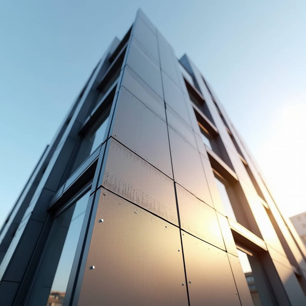
For fabrication teams and facade contractors, the gap between a Grasshopper definition and a shop-ready solid aluminium cladding panel is where most projects stall. A Rhino Aluminum Facade Model is not a rendering exercise; it is a fabrication contract. The search results point to a clear industry shift: parametric tools such as FacadeModel, FOfab, and Lunchbox are moving from concept generation toward production logic, yet the real bottleneck remains translating 2D shop drawings into 3D models that carry accurate thickness, PVDF film build, and joint geometry for solid aluminium sheets. This article walks through a practical workflow that treats the Rhino model as the single source of truth for panel nesting, brake-press allowances, and installation sequencing, then ties that data to the material standards your shop floor and site team actually need.
Why the Rhino Aluminum Facade Model Is a Fabrication Document
Most parametric tutorials stop at pattern control. A perforated or triangular panel looks compelling on screen, but the model only earns its keep when it encodes the physical constraints of a 2.0 mm or 3.0 mm solid aluminium sheet. The Rhino model should carry three layers of information: the design surface, the panel boundaries with edge returns, and the fabrication metadata such as material grade, coating specification, and bend radius. Without that third layer, the file is geometry, not a buildable model.
Fabrication plugins like FOfab directly address this by converting 2D facade shop drawings into 3D parametric fabrication models. The practical takeaway is that your Rhino Aluminum Facade Model should be built on a component library that mirrors your shop's actual press-brake and punching capabilities. If your brake press cannot hold a 15 mm return on a 3 mm sheet, the model should flag it before you issue the drawing, not after the first rejected panel arrives on site.
Building the Parametric Model Around Solid Aluminium Constraints
Start with the base sheet. Solid aluminium cladding panels are typically 1.5 mm to 3.0 mm thick, with 2.0 mm and 2.5 mm dominating commercial curtain wall work. The model must reference the neutral axis for bend allowances, because a 3 mm sheet behaves differently under a 90-degree return than a 1.5 mm sheet. Set the bend radius to 1.0 to 1.5 times the material thickness, and model the internal corner relief accordingly.
Grasshopper components such as ExtrudeData and SecExtrude, highlighted in the FacadeModel plugin, let you extrude a panel profile and cut openings in a single parametric chain. The advantage is that when the architect moves a mullion or changes a perforation pattern, the entire panel family updates without manual rework. That is the core value of a parametric Rhino Aluminum Facade Model: change one input, and the shop drawings, nesting layout, and installation schedule all stay in sync.
Perforation and Pattern Logic
For perforated facades, the attractor point technique is a reliable starting point. Divide the surface, scale the perforation density based on distance from a control point, and then map the result to physical hole diameters and spacing. The model must respect the minimum ligament between holes, which for solid aluminium sheet is typically 1.5 to 2 times the material thickness. Punching a 4 mm hole on 6 mm centres in a 3 mm sheet risks tearing the ligament; the Grasshopper definition should enforce that constraint automatically.
Open-area percentage also affects structural performance and wind load. A facade with more than 40 percent open area may need a thicker substrate or additional stiffeners. Build the open-area calculation into the model so the engineer can see the trade-off live as the pattern changes.
From Model to Shop Floor: Nesting and Flat Patterns
The Rhino Aluminum Facade Model should output a flat pattern for every panel. Solid aluminium panels are usually fabricated from flat sheet, brake-pressed into a tray with edge returns, and then stiffened with welded or riveted angles. The flat pattern must subtract the bend allowance and add the corner relief so the folded tray closes cleanly. Feeding these flat patterns directly into a nesting routine reduces scrap, which matters because solid aluminium sheet is priced per kilogram and offcuts are pure loss.
For a typical 2000 m² curtain wall with an average panel size of 1.2 m by 1.2 m, you will generate roughly 1,400 panels. A well-structured model with automatic flat-pattern output can cut drafting time by 40 to 60 percent compared with manual redrawing, and it eliminates the dimensional drift that causes field-fit problems.
Coating and Material Data in the Model
The model should carry the coating specification as metadata because it drives both cost and warranty. Solid aluminium cladding panels are finished with PVDF (polyvinylidene fluoride) coatings, typically 70 percent PVDF resin, applied at a dry film thickness of 25 to 30 microns over a primer. Some projects specify a 2-coat or 3-coat system depending on exposure. The American Architectural Manufacturers Association standard AAMA 2605 covers the highest-performance exterior coatings and is the benchmark for coastal or high-UV environments. The model should reference the specified coating class so the estimator and the coating applicator read the same requirement.
For inland projects with moderate exposure, AAMA 2604 is often sufficient and costs less. Baking this decision into the Rhino Aluminum Facade Model prevents the classic mistake where a shop quotes a 2604 coating but the spec calls for 2605, forcing a re-coat or a costly waiver.
Wind Load and Structural Verification
Solid aluminium panels are stiffened to resist wind load, and the model should support the deflection check. The European standard EN 1991-1-4 and the American ASCE 7 provide the wind pressure maps, while the panel deflection limit is usually span/60 or span/90 depending on the specifier. For a 3 mm panel spanning 600 mm between stiffeners, the allowable wind pressure is governed by the plate bending stiffness, and the model should flag spans that exceed the practical limit for the chosen thickness.
Table 1 summarises typical allowable wind pressures for solid aluminium panels at different thicknesses and stiffener spacings, based on a deflection limit of span/60 and a 6061-T6 alloy. These are planning figures; the final design must be verified by a structural engineer.
| Panel Thickness (mm) | Stiffener Spacing (mm) | Allowable Wind Pressure (kPa) | Typical Application |
|---|---|---|---|
| 2.0 | 500 | 1.4 | Low-rise, sheltered |
| 2.0 | 600 | 1.0 | Mid-rise, moderate |
| 2.5 | 600 | 1.6 | Mid-rise, exposed |
| 3.0 | 700 | 2.1 | High-rise, coastal |
| 3.0 | 800 | 1.7 | High-rise, moderate |
Installation Sequencing and Interface Detailing
The Rhino Aluminum Facade Model also serves the site team. Model the panel-to-panel joints, the drainage paths, and the interface with windows and louvers. Solid aluminium panels are typically installed with a drained and back-ventilated rainscreen system, so the model should show the cavity, the sub-structure, and the gasket or sealant joint. A joint width of 8 to 12 mm is common for thermal movement, and the model should confirm the joint accommodates the expansion calculated from the aluminium coefficient of thermal expansion of about 23 x 10⁻⁶ per °C.
For a 1.2 m panel, a 40 °C temperature swing produces roughly 1.1 mm of movement. The joint and its sealant must absorb that without cracking. The model should flag any joint narrower than the calculated movement plus a safety margin.
Quality Control and Auditing the Model
Fabrication models benefit from automated auditing. The GitHub project on Rhino architectural modeling describes a reusable skill for planning, generating, auditing, and regression-testing conceptual models. The same logic applies to a facade model: after any parametric change, re-run checks for minimum bend radius, hole ligament, joint width, and coating class. A model that validates itself before release reduces the number of shop drawing revisions and the associated cost.
For contractors who need a reliable fabrication partner, a supplier with deep experience in solid aluminium cladding and a willingness to work from your Rhino Aluminum Facade Model saves weeks of coordination. Suppliers such as Futeng® have built their process around reading client models directly, extracting flat patterns, and confirming coating and thickness before cutting sheet. That alignment between the digital model and the physical shop is what separates a smooth project from a rework-heavy one.
Closing the Loop Between Model and Material
The practical advice is to treat the Rhino Aluminum Facade Model as a living fabrication document, not a one-off design artefact. Enforce material constraints inside the Grasshopper definition, carry coating and wind-load data as metadata, output flat patterns for nesting, and audit the model after every change. When the model and the shop speak the same language, the panel count, the scrap rate, and the field-fit issues all drop. The standard references here, AAMA 2605, AAMA 2604, EN 1991-1-4, and ASCE 7, give you the external benchmarks to lock the model to real-world performance. The result is a facade that is buildable, durable, and delivered on schedule.