Building a Revit Aluminum Facade Model With Real Panel Data for Solid Aluminium Cladding
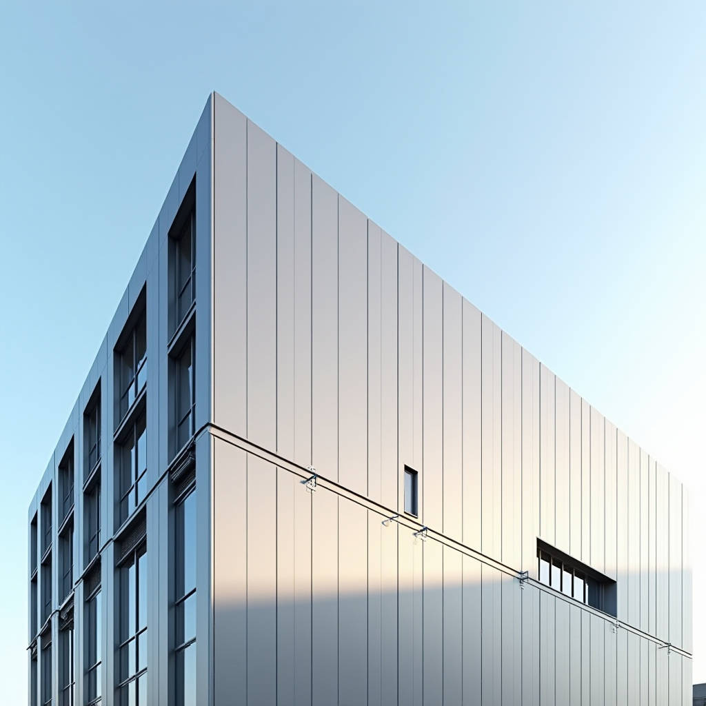
When a facade contractor opens Revit to place an aluminum cladding system, the first bottleneck is rarely the geometry. It is the data. A Revit Aluminum Facade Model built from a generic family carries no coating specification, no panel thickness, no joint tolerance, and no wind-load rating. That gap between the visual model and the fabrication reality is where cost overruns and site rework begin. This article walks through how to build a Revit Aluminum Facade Model that behaves like a real solid aluminium cladding package, with the panel parameters, connection details, and performance data that a procurement team and a curtain wall shop can actually use. We focus on solid aluminium sheets, not composite panels, and keep every figure aligned with the tolerances that a 2.0 to 3.0 mm aluminium fabricator recognizes.
Why a Generic Family Fails on a Real Facade
A facade modelled with a thin generic wall or a massing extrusion looks fine in a render and collapses during coordination. The reasons are predictable. A generic family stores no material thickness, so the cladding panel and the support system share one surface. The joint width is not parameterised, so thermal movement and drainage gaps disappear from the model. The coating is not defined, so the specification sheet cannot be generated from the model. And the fixing layout is absent, so the structural engineer cannot check the bracket spacing against the wind load.
Every one of those missing fields becomes a change order on site. A Revit Aluminum Facade Model that carries the full parameter set changes the conversation. The architect sees the panel module, the structural engineer sees the bracket grid, the procurement team sees the coating and gauge, and the fabricator sees the joint and return dimensions. One model serves all four disciplines, which is the actual point of BIM on a curtain wall project.
Core Parameters Every Solid Aluminium Panel Family Needs
Before you model a single extrusion, decide which parameters the family will expose. For solid aluminium cladding, the list below is the minimum that keeps the model useful from concept to fabrication.
- Panel thickness – 2.0 mm, 2.5 mm, or 3.0 mm. This drives weight, stiffness, and the maximum unsupported span.
- Coating system – PVDF (70/30) or FEVE, with the DFT range stored as a parameter.
- Joint width – the open or sealed gap between panels, usually 10 to 20 mm.
- Panel module – the nominal width and height of the visible face.
- Return depth – the folded edge that stiffens the panel, typically 20 to 30 mm.
- Bracket spacing – the vertical and horizontal fixing grid, which is the structural input.
- Weight per square metre – calculated from the gauge and the return geometry.
When these parameters are driven by formulas, changing the gauge from 2.0 to 3.0 mm updates the weight and the deflection check automatically. That is what separates a useful Revit Aluminum Facade Model from a static box.
Modelling the Panel as a Hosted Adaptive Family
The fastest reliable route is a curtain wall panel family hosted on a curtain wall grid. The panel family references the grid, and the grid spacing becomes the panel module. Set the panel thickness as a sweep or an extrusion with a material parameter assigned to the solid aluminium sheet. Assign a separate material to the coating so that the render and the schedule stay honest.
For the return edges, model them as part of the same extrusion rather than as separate sweeps. A single extrusion with a profile that includes the return keeps the geometry watertight and the weight calculation correct. The alternative, building the return as a separate sweep, produces a model that looks right but schedules a weight that is too low because the return volume is missing.
Joint and Movement Strategy in the Model
Solid aluminium has a coefficient of thermal expansion near 23 x 10⁻⁶ per °C. On a 6 m panel run, a 60 °C temperature swing moves the panel edge by roughly 8 mm. A Revit Aluminum Facade Model that ignores that movement will show panels butting together, which is a fabrication error waiting to happen.
Model the joint as an open gap with a defined width, and keep a parameter for the thermal allowance. For sealed joints, the backing rod and sealant depth should be part of the specification attached to the family, not a separate note. The model should also carry the drainage path at the base of each panel, because trapped water is the most common cause of coating failure on solid aluminium cladding.
Wind Load and Bracket Spacing Data
The structural input for a solid aluminium facade is the bracket grid. A 3.0 mm panel with a 20 mm return can span further than a 2.0 mm panel, so the bracket spacing is not a constant. The table below summarises practical design targets for solid aluminium panels under typical wind loads, based on the flexural strength of the aluminium alloy and the deflection limit of L/100 recommended by the curtain wall industry.
| Panel gauge | Typical max unsupported span (mm) | Bracket vertical spacing (mm) | Approx. panel weight (kg/m²) | Typical application |
|---|---|---|---|---|
| 2.0 mm | 900 | 600 | 5.4 | Low-rise, sheltered elevations |
| 2.5 mm | 1100 | 700 | 6.8 | Mid-rise, moderate wind zones |
| 3.0 mm | 1300 | 800 | 8.1 | High-rise, exposed corners |
These figures are starting points, not fixed rules. The actual bracket spacing must be checked against the site-specific wind load computed to the local code, and the deflection limit agreed with the structural engineer. The value of the model is that it makes the bracket grid a parameter, so the structural check can be run against the same geometry the fabricator will use.
Coating Performance in the Family Data
The coating is where procurement decisions get made, and where a Revit Aluminum Facade Model earns its keep. For solid aluminium cladding, the standard is a PVDF resin system with a 70/30 resin-to-pigment ratio, applied at a dry film thickness of 25 to 30 microns over a primer. The performance targets are defined in the AAMA 2605 specification, which is the highest durability class for exterior architectural coatings. AAMA 2605 requires a minimum 30-year service life, resistance to 10,000 hours of salt spray, and a colour retention and chalk resistance rating that a standard PVDF coating cannot always meet.
For projects that need even longer colour stability, an FEVE system is the alternative. FEVE offers better gloss retention in aggressive UV environments and is increasingly specified for coastal and high-altitude facades. The model should carry the coating class as a parameter, because it changes the specification, the price, and the warranty length. A procurement team that can pull the coating class straight from the model schedule saves a round of clarification emails.
Data Exchange and the Fabricator Handoff
The model is only useful if the data survives the handoff. A curtain wall fabricator rarely works natively in Revit, so the panel family must export cleanly to IFC or to a flat schedule that the shop can read. Keep the naming convention consistent, use the same panel code in the model and the shop drawing, and attach the coating and gauge data to the schedule so the fabrication order can be generated without re-entering the parameters.
This is where a supplier with a disciplined BIM catalogue helps. A manufacturer such as Futeng® publishes its solid aluminium cladding families with the panel gauge, coating class, and joint data already parameterised, so the contractor does not have to rebuild the engineering data from scratch. That reduces the modelling effort and removes a source of error between the design model and the fabrication order.
Quality Control and the Source of the Data
The reliability of a Revit Aluminum Facade Model depends on the quality of the source data. A panel family is only as good as the mill certificate, the coating test report, and the dimensional tolerance behind it. For solid aluminium sheets, the flatness tolerance and the thickness tolerance are defined in the relevant EN and ASTM standards, and the coating performance is verified against the AAMA 2605 test regime. The model should reference the test reports, not just the nominal values, so that the engineer can trace the numbers back to a certified source.
Independent testing bodies and the AAMA certification programme provide the verification trail that a procurement team needs. When the model carries those references, the facade package moves through approvals faster, because the data is already auditable.
Practical Workflow for a Facade Contractor
For a contractor starting a new project, the workflow below is the fastest path to a usable Revit Aluminum Facade Model.
- Set the panel module and joint width from the architectural drawing, not from the default grid.
- Build the panel as a hosted family with the gauge, coating, and return as parameters.
- Assign the bracket spacing from the wind load calculation, and keep it as a parameter.
- Attach the coating and material test references to the family.
- Generate the panel schedule and check the weight and coating class against the procurement spec.
- Export to IFC and share the schedule with the fabricator before fabrication starts.
Following this sequence, the model becomes a coordination tool rather than a render prop. The same geometry that drives the visualisation also drives the fabrication order, which is the only way BIM pays for itself on a cladding project.
Closing Notes on the Model
A Revit Aluminum Facade Model for solid aluminium cladding is not a modelling exercise. It is a data container that carries the panel gauge, the coating class, the joint strategy, and the bracket grid through the whole delivery chain. When those parameters are correct and traceable, the facade coordinates cleanly, the procurement spec is generated from the model, and the fabricator receives a schedule that matches the shop drawings. Start with the panel parameters, keep the bracket spacing tied to the wind load, and attach the coating certification to the family. The result is a model that the architect, the structural engineer, the procurement team, and the fabricator all trust, which is the real measure of a useful cladding BIM object.