Aluminum Facade BIM Model Data for Solid Aluminium Panel Fabrication and Coordination
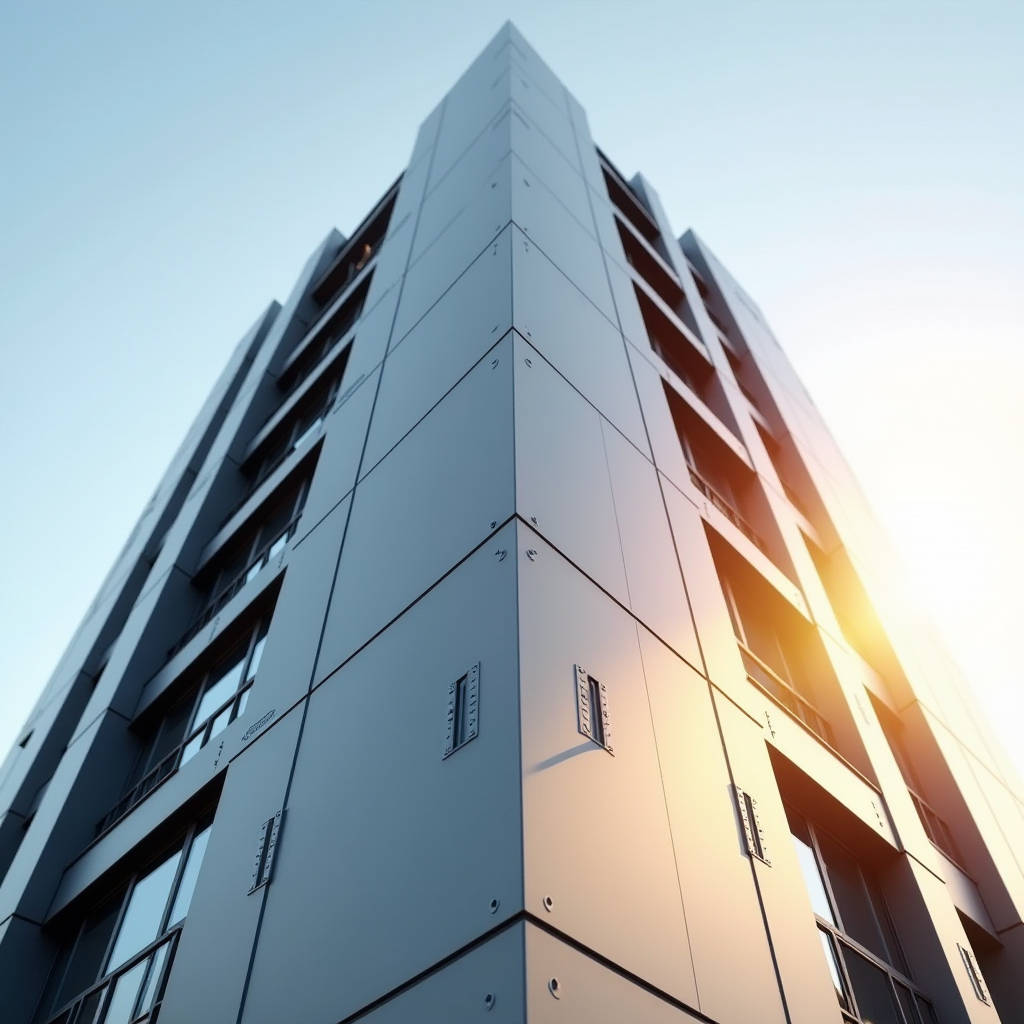
An Aluminum Facade BIM Model is more than a downloadable Revit family. For a solid aluminium cladding panel supplier, the model is the single point where geometry, material grade, coating specification, and fixing logic converge. When a facade contractor pulls a 2.0 mm solid aluminium panel family into a curtain wall assembly, the model must carry the tolerances, the PVDF film thickness, and the jointing rules that govern real fabrication. This article walks through what a genuinely useful Aluminum Facade BIM Model contains, how to audit a supplier model before it enters your federated model, and how solid aluminium panels behave differently from lightweight alternatives once you start coordinating wind loads, thermal movement, and drainage.
Why the Solid Panel Changes the BIM Conversation
Solid aluminium cladding panels are flat or shaped sheets of aluminium alloy, typically 2.0 mm, 2.5 mm, or 3.0 mm thick, finished with a PVDF or polyester coating. Unlike composite panels, a solid sheet carries its full structural contribution through its own thickness. That difference shows up in the BIM model in three places: the material definition, the fixing schedule, and the deflection checks.
In Revit, a solid aluminium panel is not a sandwich with a core. The material is a single aluminium alloy, and the model must record the alloy temper (for example 3003-H14 or 5052-H32) and the coating system. The fixing geometry also matters. A solid panel is usually edge-returned and mechanically fixed with cleats or riveted to a subframe, so the BIM family needs the return depth, the corner weld allowance, and the fastener centres. When you export that family to a structural analysis tool, the panel stiffness and the connection loads must be traceable back to the supplier's published data.
What a Useful Aluminum Facade BIM Model Actually Contains
Too many downloaded models are little more than a surface. A workable Aluminum Facade BIM Model for procurement and fabrication should carry the following data fields:
- Panel thickness and edge return geometry, with a parametric depth that can be adjusted for 2.0 mm, 2.5 mm, or 3.0 mm stock.
- Alloy and temper designation, plus the coating system (PVDF at 20–25 µm, or polyester at 25 µm) and the colour reference.
- Joint type and recommended joint width, including the thermal expansion allowance for the panel dimension.
- Fixing method, fastener type, and recommended centres, with the subframe interface identified.
- Weight per square metre, which drives handling and crane planning on site.
- Fire performance data and the relevant test standard reference.
- Fabrication constraints, such as minimum bend radius and maximum panel size for a given thickness.
A model that carries these fields lets a contractor run clash detection, quantity take-off, and even a preliminary structural check without leaving the federated model. The value is not the geometry alone; it is the metadata that turns a visual object into a procurement and fabrication document.
Coordinate the Model Against the Real Behaviour of Solid Aluminium
Solid aluminium expands roughly 23.5 × 10⁻⁶ per degree Celsius. On a 3 m panel, a 50 °C temperature swing moves the free edge by about 3.5 mm. The BIM model must reflect this in the joint width and in the fixing design, because a rigid restraint will buckle the panel. A competent model records the recommended joint width as a function of panel length, and the fixing detail must allow differential movement between the panel and the subframe.
Wind load is the second coordination point. The panel is a plate spanning between fixings, and the deflection limit for a cladding panel is commonly set at L/90 or L/100, depending on the project specification. The model should carry the panel's second moment of area, which for a solid sheet is a direct function of thickness. A 3.0 mm panel is roughly 3.4 times as stiff as a 2.0 mm panel of the same span, so the thickness choice in the model changes the allowable fixing spacing and the subframe gauge. Contractors who keep the thickness parametric can run what-if scenarios during design development instead of discovering the constraint at fabrication.
Audit a Supplier Model Before It Enters Your Federated Model
The reliability of a BIM file depends on the discipline of the supplier who published it. Before you accept a downloaded Aluminum Facade BIM Model, run a short audit against the following checks:
- Confirm the geometry matches the actual fabricated panel, including the edge return and any corner welds, not a simplified box.
- Verify the material properties are recorded in the family, not just in an accompanying PDF.
- Check that the panel is not modelled as a structural element unless the supplier has published the stiffness data to support that use.
- Confirm the fixing schedule and joint widths match the supplier's installation manual.
- Check the file version and the coordinate origin so the family sits correctly in your project grid.
Suppliers who treat BIM as a marketing afterthought publish a single generic family. Suppliers who treat BIM as an engineering deliverable publish families that carry the fabrication data and the tolerances that a curtain wall contractor actually needs. When you are evaluating a vendor for a large project, ask for the model's data schema and the revision history. A model that has been through several revisions, with documented changes to the fixing schedule or the coating specification, is a sign of a supplier who maintains the file as a live engineering record.
Data Table: Solid Panel Thickness and the Coordination Consequences
| Panel Thickness | Relative Stiffness | Typical Max Panel Size | Recommended Joint Width | Typical Fixing Centres |
|---|---|---|---|---|
| 2.0 mm | 1.0x | 1500 x 4000 mm | 10–12 mm | 300–400 mm |
| 2.5 mm | 1.95x | 1800 x 4500 mm | 12–15 mm | 350–450 mm |
| 3.0 mm | 3.38x | 2000 x 5000 mm | 15–18 mm | 400–500 mm |
The table above is a planning guide, not a substitute for a structural calculation. The joint width and fixing centres must be confirmed against the project wind zone and the panel geometry. The key point for the BIM coordinator is that thickness is a structural parameter, and the model should expose it as such.
BIM as the Bridge Between Design and Fabrication
The most common failure in facade delivery is the gap between the design model and the shop drawing. The design model shows a clean panel; the shop drawing shows the returns, the welds, the drainage holes, and the fixing cleats. A well-built Aluminum Facade BIM Model narrows that gap by carrying the fabrication details in the same object the design team uses. When the model contains the edge return and the fixing geometry, the shop drawing can be generated from the model rather than redrawn from scratch.
This also improves the quantity take-off. A model with accurate panel dimensions and the correct weight per square metre gives the procurement team a reliable material estimate. On a 10,000 m2 facade, the difference between a 2.0 mm and a 3.0 mm solid panel is roughly 40 tonnes of aluminium, which changes the crane plan, the subframe design, and the delivery schedule. Getting that decision right in the model phase saves a costly change at fabrication.
Standards and References That Anchor the Model Data
The data in a credible Aluminum Facade BIM Model should trace back to published standards. The coating performance is governed by AAMA 2605 for high-performance PVDF finishes, which specifies the film thickness and the weathering resistance. The aluminium alloy and temper should follow the relevant EN 573 or ASTM B209 designation. The panel fabrication and the tolerances for flatness and edge return are typically checked against EN 1396 or the project's own specification. Fire performance, where required, is assessed against the applicable national standard for exterior wall cladding.
For a solid aluminium panel, the PVDF coating is applied at 20–25 µm total film thickness, and the coating must be free of pinholes and defects after forming. The model should record this coating thickness, because it affects the bend radius and the handling of the panel. A panel that is specified at 2.5 mm with a 25 µm PVDF coating has a different bend behaviour than a bare sheet, and the model should carry that note.
When you are sourcing panels for a project that depends on a reliable BIM deliverable, a supplier such as Futeng® provides solid aluminium cladding panels with the coating and alloy data documented alongside the model. The point is not to advertise a brand but to note that the quality of the BIM file is a proxy for the quality of the fabrication. A supplier who publishes the alloy, the coating thickness, and the fixing schedule in the model is a supplier who has the same data on the shop floor.
Coordinate the Model With the Drainage and Ventilation Strategy
A ventilated facade system depends on a drained and ventilated cavity behind the panel. The BIM model should show the cavity depth, the drainage openings at the base, and the ventilation openings at the head. For solid aluminium panels, the cavity is typically 25–50 mm, and the model must not allow the panel to close off the drainage path. The joint design must permit water that enters the joint to drain down the back of the panel and out at the base, rather than being trapped.
The model should also flag the thermal performance of the assembly. The cavity behind a ventilated facade provides a thermal break, and the model should record the insulation layer and its position. The aluminium panel itself has a high thermal conductivity, so the insulation must be placed correctly to avoid a cold bridge. A BIM model that coordinates the panel, the cavity, the insulation, and the subframe in one assembly gives the thermal engineer a clear view of the envelope performance.
Practical Advice for the Facade Contractor
Treat the Aluminum Facade BIM Model as a living document, not a frozen download. Set a review point in your project schedule where the model is checked against the fabrication drawings and the supplier's installation manual. Ask the supplier for the revision history and the data schema, and confirm that the model's fixing schedule matches the manual. If the model and the manual disagree, resolve the discrepancy before the panel order is placed.
Keep the thickness and the joint width parametric in the model so you can run coordination checks as the design develops. Use the model to drive the quantity take-off and the subframe design, and hand the same model to the fabrication team so the shop drawings start from the coordinated geometry. A solid aluminium panel is a structural element in the facade, and the BIM model should treat it as one.
The value of a disciplined Aluminum Facade BIM Model is measured in avoided rework. When the model carries the material, the coating, the fixing, and the joint data, the design team, the procurement team, and the fabrication team work from one source of truth. That single source of truth is what turns a cladding specification into a delivered facade that meets the wind load, the thermal movement, and the drainage requirements of the project.