Aluminum Facade Fabrication Drawing for Solid Panels Covering Bend Allowance Thermal Slots and Coating Masks
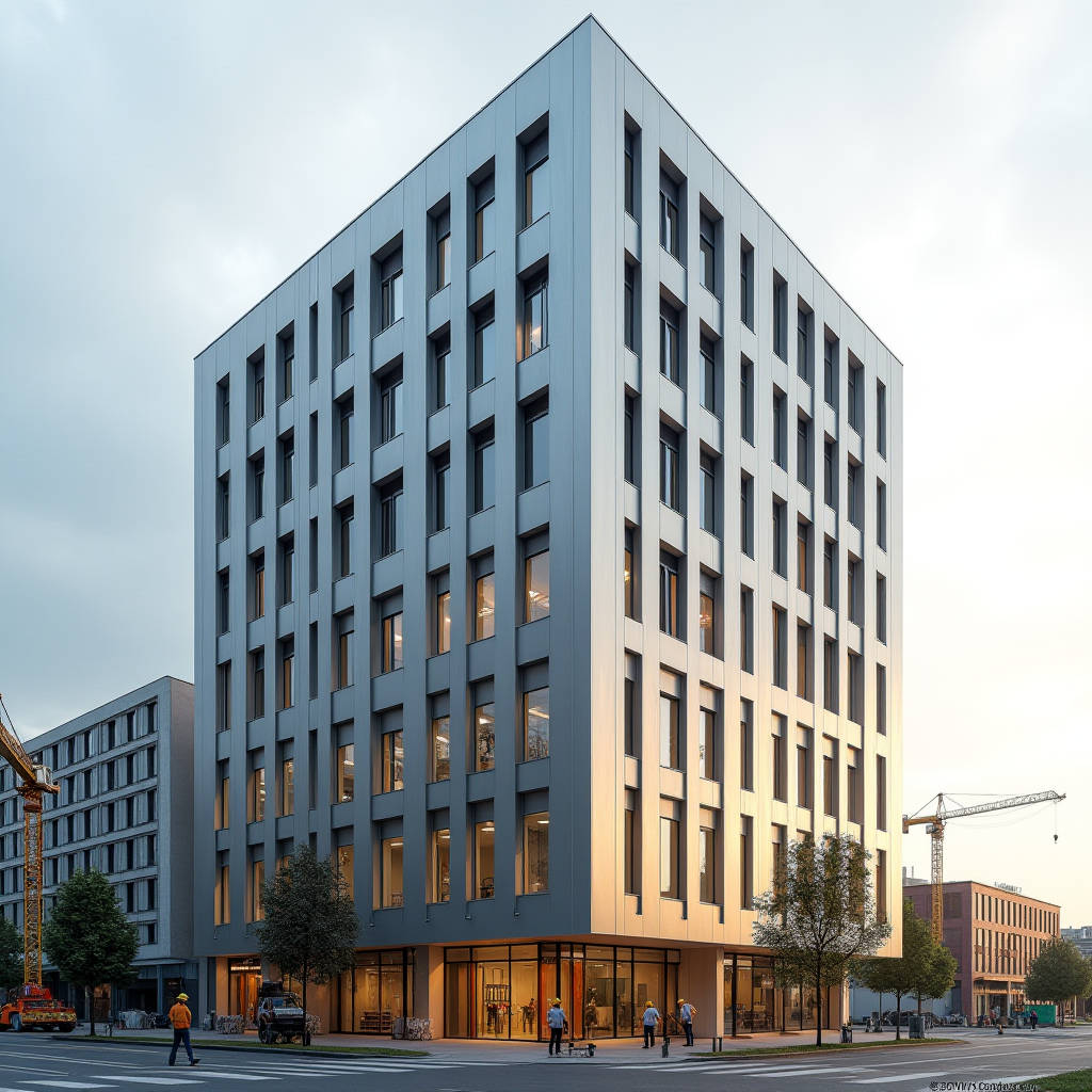
An Aluminum Facade Fabrication Drawing is the single most important document a cladding contractor will ever produce for a solid aluminium panel project. It converts the architect's intent into a shop-floor reality, dictating every cut, bend, hole, and fastener on a 2.0, 2.5, or 3.0 mm solid sheet. Get the drawing wrong and the panel fails on site, the warranty is void, and the schedule slips by weeks. Get it right and fabrication runs clean, installation is fast, and the facade performs for decades. This article walks through the specific layers of a fabrication drawing for solid aluminium cladding, the tolerances that matter, and the coordination points that most often cause rework, so your next tender and shop drawing review is grounded in verifiable engineering logic rather than guesswork.
Why the Fabrication Drawing Differs from the Shop Drawing
Too many teams treat the shop drawing and the fabrication drawing as the same deliverable. They are not. A shop drawing shows the facade in its assembled position, with mullions, brackets, and panel locations. A fabrication drawing, sometimes called a workshop drawing, is the manufacturing instruction set. It carries the panel dimensions before folding, the bend allowance, the kerf for the hem, the location of every cleat slot, the drainage weep hole coordinates, and the coating mask areas. The fabricator reads the fabrication drawing to set up the CNC punch, the press brake, and the welding jig. The installer reads the installation drawing to place the panel on the bracket grid.
When a project skips the fabrication drawing and sends the shop drawing straight to the press brake, the results are predictable: folded edges that do not align with the subframe, slotted holes that miss the anchor by 4 mm, and weep holes drilled through the wrong leg. The AAMA guidance on curtain wall and cladding documentation separates these two levels of detail for exactly this reason. A proper fabrication drawing also carries the material grade and thickness callout, the PVDF coating specification, and the surface finish class, so the production floor does not have to guess between a 2.0 mm and a 3.0 mm sheet on a high-wind zone.
Reading the Geometry of a Solid Panel Drawing
Solid aluminium cladding panels are rarely flat rectangles. Most are four-sided trays with a folded return edge, and many carry a reveal, a corner wrap, or a curved face. The fabrication drawing must communicate three distinct sets of geometry: the finished face dimensions, the developed or flat blank size, and the folded profile. The finished face is what the architect sees. The developed blank is what the sheet arrives as before bending. The difference between the two is the bend allowance, which depends on the aluminium alloy, the sheet thickness, and the inside bend radius.
For a 2.0 mm solid sheet bent to a standard inside radius of 3.0 mm, the bend allowance typically lands near 3.5 mm per bend. A 3.0 mm sheet with a 4.5 mm inside radius runs closer to 5.2 mm per bend. These numbers shift with the temper and the tooling, so a reliable fabricator recalibrates the allowance on the actual press brake rather than trusting a textbook value. The drawing should state the bend allowance explicitly, because a 0.5 mm error on each of four bends compounds into a 2 mm error on the finished panel, which is enough to break the reveal alignment across a 12 m elevation.
Fastener and Support Coordination
The fabrication drawing is where the panel meets the subframe. For solid aluminium cladding, the common support methods are concealed cleats, exposed screw fixing, and cassette-style interlocking systems. Each method changes what the drawing must show. Concealed cleats require a slot or a hook profile on the return leg, with the slot length calculated to allow thermal movement. Aluminium expands roughly 0.024 mm per metre per degree Celsius, so a 3 m panel across a 60 °C temperature swing moves about 4.3 mm. The cleat slot and the fixing hole must accommodate that travel without binding, or the panel will buckle and the coating will craze at the corners.
The drawing should also flag the fixing centres and the edge distance. A typical solid panel fixing sits at 300 mm centres along the return leg, with a minimum edge distance of 20 mm from the hole centre to the folded edge. The fastener type, whether a stainless steel self-tapping screw into an aluminium bracket or a rivet through a cleat, must be specified with its diameter and length. Mixing a 4.8 mm rivet where the drawing calls for a 5.0 mm screw is a classic site substitution that leads to loose panels and rattling in wind.
Drainage and Ventilation Detailing
A ventilated facade is only as good as its drainage path, and that path is defined on the fabrication drawing. The drawing must show the weep holes, their diameter, their position on the lower return leg, and the insect mesh requirement. A common standard is a 5 mm weep hole at 600 mm centres on the bottom leg, positioned so water drains outboard of the vapour barrier. The drawing should also indicate the open joint width between panels, typically 10 to 15 mm for a ventilated system, and the baffle or gasket that keeps the cavity pressure equalised.
If the weep holes are omitted from the fabrication drawing, the installer will either drill them on site, which risks damaging the coating and the drainage membrane, or skip them entirely, which traps condensation inside the cavity and promotes corrosion of the steel subframe. The ISO 52022 series on thermal and solar performance of building components is a useful reference for cavity dimensions and ventilation rates, and it feeds directly into the drawing's cavity width callout.
Coating and Masking Callouts
Solid aluminium panels are typically finished with a two-coat or three-coat PVDF system, with a dry film thickness of 25 to 35 microns for the two-coat system and 35 to 45 microns for the three-coat system. The fabrication drawing must carry this specification, along with the colour reference and the gloss level, because the coating is applied before the panel is formed. Bending a coated sheet cracks the film at the bend line unless the coating is designed for post-forming, so the drawing must call out which edges are pre-formed and which are cut after coating.
The drawing also needs a masking plan. Areas that must remain bare for welding, earthing, or adhesive bonding are masked before coating. A clear callout of the masked zones prevents the coater from blanketing the entire panel, which would leave the fabricator with a coated surface that cannot be welded or bonded. The AAMA 2605 specification for high-performance organic coatings on aluminium is the benchmark for PVDF performance, and referencing it on the drawing gives the coating supplier an unambiguous acceptance criterion.
Dimensioning and Tolerancing That Survives the Shop Floor
A fabrication drawing fails when it is over-dimensioned. A panel with forty dimension strings looks precise but is impossible to inspect, and the CNC program ends up reading the wrong reference. The drawing should use a single datum scheme, dimension from one edge or one corner, and keep the total tolerance stack predictable. For solid aluminium cladding, a practical fabrication tolerance is plus or minus 1.5 mm on the finished face dimension, plus or minus 1.0 mm on the hole position, and plus or minus 0.5 mm on the bend angle. These numbers are achievable on a modern CNC press brake and are tight enough to keep the reveal grid clean.
The drawing must also carry a flatness and squareness tolerance. A 3.0 mm solid sheet is stiff, but a large panel can still bow during handling. The drawing should state a maximum deviation of 2 mm over a 2 m straightedge on the finished face. This is the number the quality inspector checks before the panel is crated, and it is the number that prevents a beautiful facade from looking wavy in low-angle sunlight.
BIM Coordination and the Digital Fabrication Drawing
Modern cladding projects run the fabrication drawing through a BIM workflow, where the panel geometry, the subframe, and the fixing layout live in a federated model. The value of this is clash detection before the drawing is issued. A bracket that collides with a steel beam, or a panel edge that overlaps a window frame, is caught in the model instead of on the truck. The ISO 19650 series on information management for the built environment provides the framework for exchanging these models between the architect, the facade engineer, and the fabricator.
When the fabrication drawing is generated from the BIM model, the panel is cut, folded, and drilled from the same geometry that was clash-checked. This removes the classic translation error where the 2D drawing drifts from the 3D model. The drawing should carry a model revision reference and a level of geometry definition so that the shop floor and the site team are working from the same digital truth. Futeng® supplies solid aluminium cladding panels to contractors who run this exact workflow, and their fabrication teams routinely verify that the drawing's bend allowance and fixing slots match the press brake tooling before a single sheet is cut.
Comparative Data for Coating and Support Selection
The table below summarises the practical parameters that a fabrication drawing must carry for solid aluminium cladding, so the specifier and the fabricator agree on the acceptance criteria before production begins.
| Parameter | 2.0 mm Solid Panel | 2.5 mm Solid Panel | 3.0 mm Solid Panel |
|---|---|---|---|
| Typical bend inside radius | 3.0 mm | 3.5 mm | 4.5 mm |
| Approx. bend allowance per bend | 3.5 mm | 4.3 mm | 5.2 mm |
| Max panel width before stiffening | 1,200 mm | 1,500 mm | 1,800 mm |
| Fixing centre spacing | 300 mm | 300 mm | 300 mm |
| PVDF two-coat DFT | 25-35 microns | 25-35 microns | 25-35 microns |
| PVDF three-coat DFT | 35-45 microns | 35-45 microns | 35-45 microns |
| Flatness deviation over 2 m | 2 mm max | 2 mm max | 2 mm max |
| Typical wind load capacity range | 1.2-1.8 kPa | 1.6-2.4 kPa | 2.0-3.0 kPa |
The wind load figures assume a standard 600 mm subframe grid and concealed cleat fixing. They are indicative for early budgeting and should be verified with a wind tunnel or code-based calculation for the specific site and building height, using the local wind code and the ASTM E330 structural performance test as the acceptance basis.
Common Rework Traps and How the Drawing Prevents Them
Most cladding rework on solid aluminium projects traces back to four drawing failures. The first is a missing bend allowance, which produces panels that are short on the finished face and cannot close the reveal. The second is an undefined thermal slot, which leaves no room for expansion and causes the panel to buckle or the coating to crack. The third is an ambiguous fixing callout, where the site substitutes a fastener that does not match the drawing and the panel loosens. The fourth is a coating mask that is not drawn, leaving the fabricator unable to weld or bond the panel.
A fabrication drawing that carries all four details, with explicit tolerances and a single datum, turns the shop floor into a repeatable process. The quality inspector checks against the drawing, the CNC program reads the drawing, and the installer trusts the drawing. This is the difference between a facade that goes up in weeks and one that drags on through a season of site rework.
Closing Engineering Advice
Treat the Aluminum Facade Fabrication Drawing as a contractual deliverable with the same weight as the structural calculation, not as an internal convenience. Require it for every solid aluminium panel, even the flat ones, because the flat panel still needs a bend allowance, a fixing slot, and a coating mask. Issue it for review before any sheet is cut, and hold the fabricator to the tolerances printed on it. Reference AAMA 2605 for the coating, ASTM E330 for the structural performance, and ISO 19650 for the digital coordination. When the drawing is right, the panel is right, and the facade performs for the life of the building.