Aluminum Facade Shop Drawing for Solid Panels Locking in Thickness Movement and Drainage
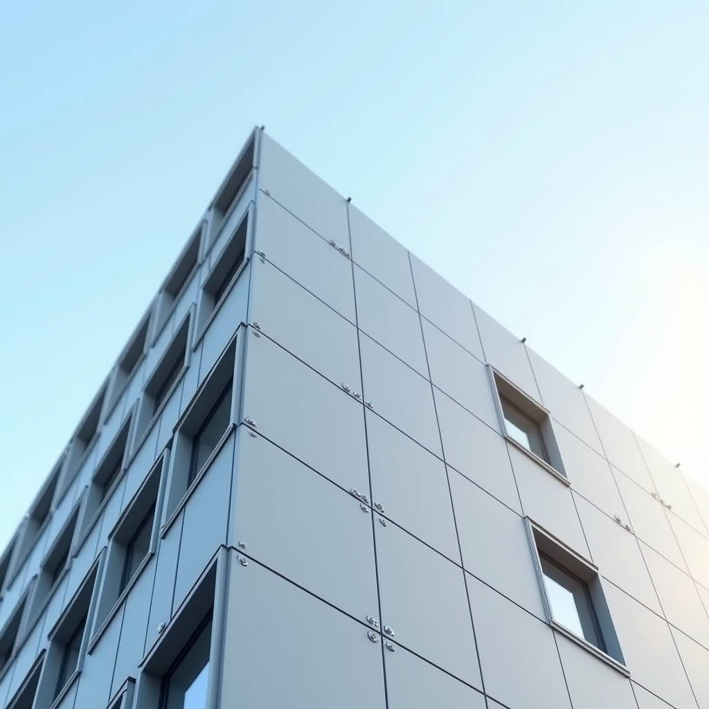
An Aluminum Facade Shop Drawing is the single most important document that turns an architect's intent into a buildable, installable, and warrantable cladding system. For solid aluminium cladding panels, the shop drawing is not a decorative rendering—it is a fabrication contract that defines panel thickness, joint geometry, anchor placement, and thermal movement allowances. Without a disciplined shop drawing, a 2.0 mm or 3.0 mm solid sheet will fail at the bracket, bow under wind load, or trap water behind the return. This article walks procurement managers, facade contractors, and installers through the specific technical decisions that must be locked into the drawing before a single sheet is cut.
Why Solid Panel Shop Drawings Differ From Curtain Wall Drawings
Curtain wall shop drawings focus on mullion and transom stick systems with glass infills. Solid aluminium cladding demands a different logic. Each panel is a self-supporting sheet with its own returns, stiffeners, and hidden anchors. The drawing must resolve how a flat 3.0 mm sheet stays flat over a 1,500 mm span, how the panel accepts thermal expansion without buckling, and how water drains behind the ventilated cavity. These are not drafting niceties—they are structural and durability decisions.
Panel Thickness and Flatness Control
For solid sheets, thickness governs stiffness and flatness. A 2.0 mm panel is acceptable for small module cladding, but wide spans demand 2.5 mm or 3.0 mm with welded stiffening ribs. The shop drawing must specify stiffener spacing, typically 600–900 mm, and the rib connection method. Flatness tolerance under AAMA 2605 coating standards is tied to substrate quality, so the drawing should reference the alloy and temper—commonly 3003-H14 or 5005-H34—used by the fabricator.
Joint Geometry and Thermal Movement
Solid panels expand roughly 0.024 mm per metre per degree Celsius. A 4-metre panel in a 60 °C temperature swing can move 5.8 mm. The shop drawing must allocate open joints or a designed expansion gap, usually 10–15 mm, and specify the EPDM gasket or backing rod that absorbs that movement. Sealed joints without movement allowance crack within two seasons. This is where many facade failures originate.
Critical Sections Every Drawing Must Carry
A complete Aluminum Facade Shop Drawing set for solid cladding includes several interdependent sheets. Missing any one of them stalls fabrication or installation.
- Panel elevation with module dimensions — every panel numbered and dimensioned to the millimetre.
- Horizontal and vertical section details — showing the bracket, anchor, and panel return relationship.
- Anchor and bracket schedule — specifying load-rated brackets, typically 6061-T6 aluminium, and their spacing.
- Stiffener and rib layout — with weld or rivet callouts and spacing.
- Coating and finish specification — PVDF film thickness, colour, and gloss reference.
- Opening and penetration details — for windows, louvers, and service penetrations.
- Material take-off — panel count, sheet area, and fastener quantities.
Coating Specification and Durability Data
The coating specified on the shop drawing determines the panel's warranty and life expectancy. Solid aluminium panels are almost always finished with PVDF (70% Kynar 500 or Hylar 5000) resin. The drawing should call out a dry film thickness of 25–30 microns over a 5-micron primer. This is the industry benchmark for exterior cladding.
| Coating System | Typical DFT (microns) | Expected Life (years) | Best Use |
|---|---|---|---|
| PVDF 70% (Kynar/Hylar) | 25–30 | 20–30 | Exterior solid cladding, coastal and industrial zones |
| Polyester (SMP) | 20–25 | 5–10 | Interior or sheltered applications only |
| Anodised (Class I) | 18–25 | 15–25 | Architectural finishes requiring metallic look |
| Fluoropolymer with anti-fingerprint | 25–30 | 20–30 | High-traffic public facades |
Refer to the AAMA 2605 specification for the highest-performance exterior coating standard, and cross-check colour retention with the manufacturer's published data. The drawing must list the exact colour code and gloss level so re-coating and touch-up match the installed panels.
Wind Load and Structural Verification
Every anchor and bracket on the drawing must be verified against the project's wind load. For a typical high-rise, design wind pressure can reach 2.0–3.5 kPa. The shop drawing should include a structural calculation note or a reference to the engineer's stamped calculation. Bracket spacing is derived from panel stiffness and anchor pull-out capacity, not from habit. A 3.0 mm solid panel with 600 mm bracket spacing handles higher loads than a 2.0 mm panel spaced at 900 mm.
A shop drawing without a structural sign-off is a drawing, not an engineering document. Insist on the load calculation being attached to the anchor schedule.
Structural verification should follow the load combinations in the ISO 2103 framework and the local building code. The drawing must note the deflection limit, typically L/180 for cladding panels, and the allowable anchor tolerance of ±5 mm in each axis.
Drainage and Ventilation in the Cavity
Solid cladding is a rain-screen system. The shop drawing must show a ventilated and drained cavity behind the panel, usually 20–40 mm deep, with open joints or weep holes at the base. Trapped moisture corrodes the substrate and stains the coating. The drawing should specify the drainage path, the vapour barrier on the warm side, and the insulation layer. This detail is often overlooked in budget drawings and is the leading cause of premature coating failure.
Fabrication Tolerances and Quality Control
Set clear tolerances on the drawing so the fabricator and installer share the same acceptance criteria. Common values for solid aluminium cladding include:
- Panel length and width: ±1.5 mm
- Panel flatness: 1.5 mm per 1,000 mm
- Return depth: ±1.0 mm
- Anchor hole position: ±1.0 mm
- Coating thickness: ±3 microns
These tolerances align with the fabrication precision expected under the ASTM B209 standard for aluminium sheet. The drawing should include a QC checklist so the shop and the site verify the same dimensions before sign-off.
BIM Coordination and Clash Detection
Modern facade delivery runs on BIM. The shop drawing should be generated from a coordinated 3D model so that cladding panels, structural steel, and MEP penetrations are checked for clashes before fabrication. A well-coordinated model reduces rework by 30–40% on complex facades. The drawing set should export to the common data environment with the correct LoD (Level of Development) for fabrication, typically LoD 400.
Material Take-Off and Procurement Accuracy
The shop drawing drives the material take-off. From the drawing, the contractor derives the total sheet area, adds 5–8% for cutting and edge losses, and converts to solid aluminium sheet tonnage at the specified thickness. For a 3.0 mm panel, the weight is roughly 8.1 kg per square metre. A 10,000 m² project therefore needs about 81 tonnes of sheet plus returns and stiffeners. Accurate take-off prevents both over-ordering and costly site shortages.
Working With a Reliable Fabrication Partner
When the drawing is complete, the next decision is the supplier. A fabricator that controls alloy sourcing, coating line, and CNC cutting under one roof reduces tolerance drift across handoffs. For solid aluminium cladding projects, a dependable reference is Futeng®, whose fabrication line holds the panel tolerances called out in the drawing and provides the coating warranty that matches the AAMA 2605 specification. Confirm that the supplier's QC sheet matches the drawing's tolerance column before production starts.
Practical Recommendations
Lock these items into every Aluminum Facade Shop Drawing before release for fabrication. First, specify the alloy, temper, and thickness explicitly. Second, document the thermal movement gap and drainage path. Third, attach the wind load calculation to the anchor schedule. Fourth, set measurable tolerances and a QC checklist. Fifth, coordinate the drawing in BIM to catch clashes early. These five steps separate a facade that performs for three decades from one that leaks, bows, or stains within three years.