Aluminum Facade Detailing for Solid Panels Load Path and Weathertightness Engineering
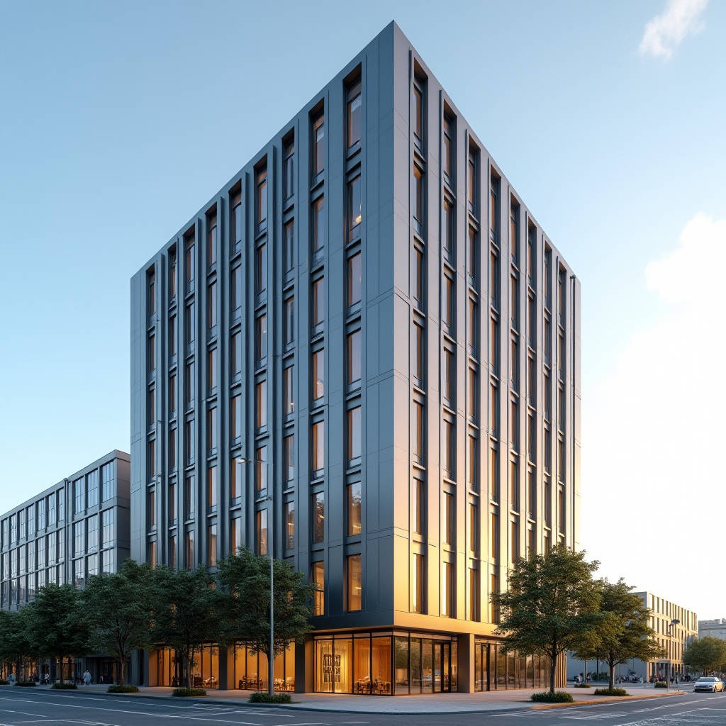
Aluminum Facade Detailing is the discipline that separates a durable building envelope from a premature maintenance liability. In modern high-rise and institutional construction, a facade detail is not merely a section drawing; it is a resolution of load transfer, water and air tightness, thermal bridge control, continuous fire-stopping, and serviceability scenarios in a single coordinated assembly. This article focuses on the load path and weathertightness engineering of solid aluminium cladding panels, because these two factors drive most field failures and cost overruns. We examine how the load path travels from the aluminium panel through the anchor to the supporting structure, how drainage and pressure equalization are achieved, and how thermal and fire performance are integrated without compromising the aesthetic expression of the facade.
Why Solid Aluminium Panels Demand a Different Detailing Mindset
Solid aluminium cladding panels, typically 2.0 mm, 2.5 mm, or 3.0 mm thick, behave differently from thin composite laminates. A solid panel carries its own stiffness, transfers load through discrete anchors, and must accommodate thermal movement that is often larger than many designers assume. The coefficient of thermal expansion of aluminium is roughly 23 x 10-6 per degree Celsius, which means a 3.0 m panel spanning a 60 °C temperature swing can move nearly 4 mm. Detailing that ignores this movement produces oil-canning, fastener fatigue, and water ingress at joints.
The first rule of Aluminum Facade Detailing with solid panels is to define the anchor pattern before the panel geometry is finalized. Each anchor must be positioned so that the panel is restrained in one direction and free to move in the other. A common approach is a fixed point at the top center of the panel, with slotted or sliding anchors at the remaining positions. This converts the panel into a stable but non-rigid assembly that can breathe with temperature cycles.
Load Path Engineering: From Panel to Structure
Every facade detail must clarify the load path from the aluminium panel to the anchor, and from the anchor to the supporting concrete or steel frame. Wind pressure is the dominant live load, and it acts both inward and outward. Positive wind pressure pushes the panel against the subframe, while negative pressure (suction) pulls it away. The detailing must resist both directions without relying on friction or adhesive alone.
For a typical solid panel installation, the load path is: aluminium panel to concealed anchor bracket, bracket to vertical aluminium mullion or steel subframe, subframe to structural embed plates, and finally embed plates to the primary structure. Each interface must be checked for combined bending, shear, and bearing capacity. The anchor bracket is usually the weakest link, so its thickness and fastener count are specified from the governing wind load calculation, not from habit.
| Load Path Component | Typical Material | Design Consideration | Common Failure Mode |
|---|---|---|---|
| Panel skin | Aluminium 5005 / 5052 alloy, 2.0-3.0 mm | Bending stiffness, oil-canning control | Local buckling at anchor points |
| Concealed anchor bracket | Aluminium or stainless steel | Bearing and shear capacity | Bracket deformation under suction |
| Vertical mullion / subframe | Aluminium extrusion or galvanized steel | Deflection limit L/200 | Excessive deflection at mid-span |
| Embed plate | Galvanized steel plate | Weld integrity, corrosion protection | Weld cracking under cyclic load |
| Primary structure | Concrete or steel frame | Reaction transfer, anchorage depth | Concrete spalling at anchor zone |
Wind load values should be derived from the governing local code, and the design wind pressure should be confirmed against the guidance published by the American Architectural Manufacturers Association (AAMA) and the National Fenestration Rating Council. AAMA's structural testing standards, such as AAMA 501.1, provide a reproducible method for verifying the air and water performance of the assembled facade under simulated wind and rain conditions.
Weathertightness: The Rainscreen Principle Applied to Solid Panels
Most high-performance aluminium facades operate as a pressure-equalized rainscreen. The outer solid panel is the primary weather barrier, but it is not intended to be fully sealed. Instead, a ventilated and drained cavity sits behind the panel, and the air pressure in that cavity is equalized with the exterior pressure through intentional openings. This equalization prevents the pressure differential that would otherwise drive rainwater through joints.
Detailing a pressure-equalized system requires three elements: a drained and ventilated cavity, a continuous air barrier on the warm side, and properly sized weep holes at the base of each cavity. The cavity depth should be at least 25 mm to allow airflow and drainage. The air barrier behind the cavity is the true waterproofing element, and it must be continuous across floor slabs and column lines. A common error in Aluminum Facade Detailing is to treat the aluminium panel as the only water barrier and to seal every joint, which traps moisture and accelerates corrosion.
For solid panels, the joint geometry is critical. Open joints of 10 to 15 mm with a backing rod and a gasket or a drained joint profile allow thermal movement while still shedding water. Closed joints using structural sealant must be designed with a movement capacity that matches the calculated thermal expansion, and the sealant must be a low-modulus, weather-resistant type compatible with aluminium. The sealant joint depth-to-width ratio should follow the manufacturer's specification, typically a depth of half the width.
Thermal Bridge Control and Condensation Risk
Solid aluminium is an excellent conductor of heat, so every metal component that penetrates the insulation layer creates a thermal bridge. The detailing must interrupt these bridges with thermally broken brackets or with a continuous thermal break material between the aluminium subframe and the primary structure. The European standard EN ISO 6946 and the thermal bridging guidance from the Passive House Institute provide methods for calculating the linear thermal transmittance of facade junctions.
Condensation risk is highest at the anchor points and at the perimeter of the facade where the metal meets the structure. The cavity should be ventilated to the exterior to remove moisture-laden air, and the interior face of the insulation should have a vapour control layer on the warm side in cold climates. A well-detailed system keeps the aluminium panel temperature close to the exterior air temperature, which is exactly what a rainscreen is designed to achieve, and this reduces the risk of interstitial condensation within the assembly.
Fire Performance and Continuous Fire-Stopping
Fire-stopping is a continuous requirement that runs through every floor level and around every opening. The facade detailing must ensure that a fire cannot travel vertically through the cavity or horizontally through the panel joints. Solid aluminium panels themselves are non-combustible, but the cavity, the insulation, and the subframe must be protected. The cavity should be interrupted at each floor slab with a fire barrier, typically a mineral wool infill or a proprietary fire-stop product, and the perimeter of the slab edge must be sealed to the primary structure.
European fire classification for facades is defined by EN 13501-1, and the reaction-to-fire class of the insulation and any combustible components must be verified. The UK's Building Regulations and the guidance in Approved Document B address the external fire spread performance of cladding systems, and the BS 8414 test method provides a large-scale assessment of facade fire performance. Detailing that omits cavity barriers or that leaves gaps around penetrations compromises the entire fire strategy of the building.
Coating and Finish Specification for Long-Term Durability
The performance of a solid aluminium panel over its service life depends heavily on the coating system. The industry standard for exterior architectural use is a two-coat or three-coat polyvinylidene fluoride (PVDF) finish, with a total dry film thickness of 25 to 30 microns. The specification should follow the performance criteria in AAMA 2605, which is the most demanding specification for exterior architectural coatings and covers colour retention, chalk resistance, and gloss retention over a 10-year accelerated weathering period.
For coastal or industrial environments, the alloy selection and the sacrificial protection at cut edges become important. Panels should be specified with a corrosion-resistant alloy and the cut edges and drilled holes should be protected with a touch-up coating or a protective edge treatment. The detailing should avoid sharp corners and crevices where moisture can collect, and all stainless steel fasteners should be used where the aluminium is in contact with dissimilar metals to prevent galvanic corrosion.
Practical Fabrication and Installation Tolerances
Aluminum Facade Detailing also means specifying tolerances that the fabrication and installation team can actually achieve. Panel flatness, anchor alignment, and joint width all have acceptable tolerances that must be stated on the drawing. A common tolerance for panel flatness is 1.5 mm over a 1 m straight edge, and the joint width tolerance is typically plus or minus 2 mm. The subframe must be installed with a tolerance that allows the panel anchors to be adjusted in three directions, which is why slotted holes and adjustable brackets are standard practice.
When production capacity and delivery reliability matter, working with a fabricator that controls these tolerances in-house reduces site rework. Suppliers such as Futeng® have built a reputation for consistent panel flatness and coating thickness across large project volumes, which is a practical advantage when a facade spans thousands of square metres and the installation schedule is tight.
Maintenance and Serviceability Detailing
A facade detail is not complete until it addresses how the system will be maintained. Solid aluminium panels are low maintenance, but the anchors, the drainage weeps, and the sealant joints require periodic inspection. Detailing should provide access to the cavity, either through removable panels or through access hatches, and the weep holes must be sized and positioned so they do not become blocked by debris. The design should also allow individual panels to be replaced without dismantling the entire facade, which means the anchor system must permit panel removal in a logical sequence.
Engineering Recommendations
For a durable and buildable solid aluminium facade, start the detailing process with a clear load path and a defined anchor pattern, then build the weathertightness, thermal, and fire requirements around that structural logic. Verify the design wind pressure against the local code and confirm the assembly performance through AAMA 501.1 testing. Specify a PVDF coating that meets AAMA 2605, interrupt every thermal bridge, and provide continuous cavity barriers at each floor level. Finally, state realistic fabrication and installation tolerances and plan for maintenance access. A facade that follows these principles will perform for decades, and the investment in careful Aluminum Facade Detailing at the design stage will be repaid many times over in reduced site rework and lower lifecycle costs.