Aluminum Facade Performance Mockup Testing for Solid Aluminium Panel Systems
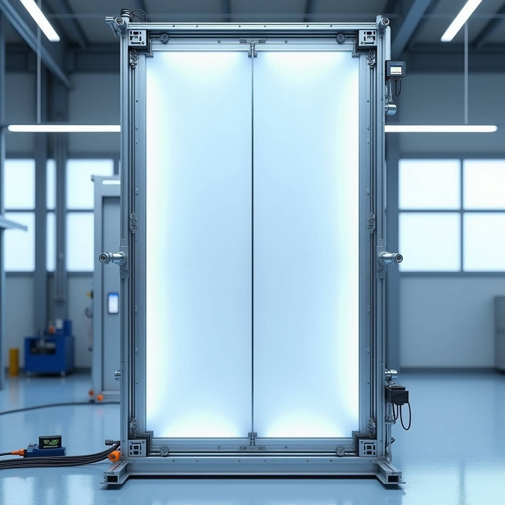
An Aluminum Facade Performance Mockup is the single most reliable way to de-risk a curtain wall before a single production batch is cut. For general contractors, facade installers, and procurement teams working with solid aluminium cladding panels, the gap between shop drawings and site reality is where cost overruns hide. A full-scale performance mockup closes that gap by testing water infiltration, air leakage, structural deflection, and thermal behaviour under controlled laboratory conditions. This article walks through how to scope, sequence, and read a performance mockup for solid aluminium panel systems, what tolerances actually matter, and where the testing budget delivers the highest return. The goal is practical: give project teams a defensible framework for turning mockup results into production decisions and warranty protection.
Why a Performance Mockup Outperforms a Visual Sample
Many projects stop at a visual mockup, a small corner panel that confirms colour and joint aesthetics. That step is useful for sign-off, but it tells you nothing about how the assembly behaves under wind, rain, and thermal cycling. A true Aluminum Facade Performance Mockup is a full-scale specimen of the actual wall assembly, built with production-grade solid aluminium panels, the real gaskets, the actual drainage cavity, and the specified anchorage. It is installed on a test rig that can simulate structural loading and water spray conditions.
The distinction matters because solid aluminium cladding panels fail in ways that are invisible on a flat sample. A 2.0 mm or 3.0 mm panel can appear perfectly flat in a showroom, yet develop oil-canning under negative wind pressure when its stiffening ribs are spaced too far apart. A gasket can look fine in a sample box, yet leak at the splice when the building frame racks under live load. Only a full-scale mockup exposes these interactions.
What the Test Actually Measures
Standard performance mockup testing for aluminium facade systems follows the AAMA 501 series and ASTM E330, E283, and E331 protocols. Depending on the project specification, the rig will run a sequence of tests that typically include:
- Air infiltration (ASTM E283): measures airflow through the assembly at a specified pressure differential, usually 75 Pa.
- Water penetration (ASTM E331): a static spray test at a set pressure, typically 300 Pa, for 15 minutes.
- Structural performance (ASTM E330): applies positive and negative wind loads to verify deflection limits, usually L/175 for the supporting frame and L/60 for the cladding.
- Thermal transmission (ASTM C1363 or guarded hot box): validates U-value claims for the insulated cavity behind the panels.
- Inter-story movement and seismic racking: simulates floor-to-floor drift and lateral building movement.
These are not optional extras. Regulatory bodies and many local building codes now expect documented performance evidence before a facade is released for production. Passing the mockup is often a precondition for the final shop drawing approval and for the issuance of a certificate of occupancy later in the project.
Reading the Numbers: What Pass Means
A passing result is not a single number. It is a set of thresholds that must hold simultaneously. The table below summarises typical acceptance criteria for a solid aluminium panel facade, based on common project specifications and the AAMA/ASTM framework.
| Test Parameter | Standard Reference | Typical Acceptance Criterion | Why It Matters on Site |
|---|---|---|---|
| Air infiltration | ASTM E283 | ≤ 0.3 L/s·m² at 75 Pa | Controls energy loss and interior condensation risk |
| Water penetration | ASTM E331 | No water crossing the plane at 300 Pa | Prevents interior damage and mould claims |
| Positive wind load | ASTM E330 | No permanent deformation at 1.5× design load | Guarantees panel flatness under storm events |
| Negative wind load | ASTM E330 | No oil-canning or fastener pull-out at 1.5× design load | Protects against panel dishing and fastener fatigue |
| Inter-story drift | ASTM E2128 / AAMA 501.4 | No gasket failure at design drift ± | Prevents water ingress at floor slabs during seismic events |
| Thermal U-value | ASTM C1363 | Matches design within ±10% | Supports energy code compliance and warranty |
Notice that the structural tests are run at 1.5 times the design load. This safety factor is not decorative; it accounts for load path uncertainty, fastener tolerance, and panel stiffness variation. If the mockup passes at this multiplier, the production assembly has a realistic margin against the worst-case site condition.
Panel Thickness and Stiffener Spacing
For solid aluminium cladding panels, the two variables that dominate structural performance are sheet thickness and stiffener (rib) spacing. A 2.0 mm panel with ribs at 600 mm centres behaves very differently from a 3.0 mm panel with ribs at 400 mm centres. The mockup is where you validate that the chosen combination meets the deflection limit without over-engineering.
As a working estimate, a 2.0 mm solid aluminium panel spanning 600 mm between ribs will typically deflect more than a 2.5 mm panel under the same negative pressure. The difference is roughly proportional to the cube of the thickness ratio, which means a 25% increase in thickness (from 2.0 to 2.5 mm) cuts deflection by nearly 40%. That is the kind of interaction a mockup reveals with real numbers, not guesswork.
For coastal projects with high wind zones, most experienced facade engineers specify 2.5 mm or 3.0 mm panels with rib spacing held at 400 to 500 mm. The PVDF coating thickness, typically 25 to 30 microns total on the exterior face, is a separate concern from structural performance, but it must be verified on the mockup too, because coating delamination under cyclic loading is a known failure mode.
Sequencing the Mockup into the Project Schedule
The biggest mistake teams make is treating the performance mockup as a late-stage checkpoint. It should be scheduled before the main production run, ideally after the shop drawings are 80% complete but before the final approval. That timing gives the design team room to adjust stiffener spacing, gasket profiles, or anchorage details without scrapping a production batch.
A realistic timeline for a single-storey mockup is four to six weeks from drawing freeze to test report, including fabrication, rig setup, and the test sequence itself. If the project is a high-rise with multiple typical floors, some teams build a two-storey mockup to capture the inter-story movement behaviour. That adds roughly two weeks. Procurement teams should lock the mockup schedule into the overall facade programme early, because a failed test can add three to four weeks of rework and retest.
When selecting a fabrication partner, the mockup must be built by the same crew and with the same tooling that will handle production. A mockup built by a different shop with different tolerances tells you nothing about the production quality. This is where a reliable supplier such as Futeng® earns its place, because their fabrication and testing workflow is consistent between the mockup and the production run.
Common Failure Points and How to Avoid Them
After reviewing hundreds of mockup reports, a few failure modes recur with enough frequency that they deserve explicit attention:
- Gasket splice leaks. Horizontal and vertical gasket junctions are the weak link. Specify factory-vulcanised corners wherever possible, and test the mockup with the same jointing method planned for production.
- Fastener pull-out under negative pressure. This usually traces to undersized fasteners or soft backing material. Verify the screw engagement length against the actual substrate on the mockup.
- Oil-canning on large panels. Panels wider than 1500 mm need either a thicker sheet or a stiffening strategy. The mockup is the place to confirm the visual result under load, not just the deflection number.
- Drainage cavity blockage. If the weep holes or drainage slots are obstructed by sealant or debris, water sits in the cavity and finds its way inside. The mockup test will expose this during the water spray phase.
Each of these failures is cheap to fix on a mockup and expensive to fix on a completed tower. That is the entire economic argument for investing in the test.
Budgeting the Mockup Correctly
A full-scale performance mockup for a typical office tower facade runs between 0.5% and 1.5% of the total facade package cost, depending on the number of tests and the complexity of the assembly. For a facade package worth USD 2 million, that translates to USD 10,000 to USD 30,000. Spread across the risk it eliminates, that is one of the highest-return expenditures in the project.
The cost breaks down roughly into three parts: fabrication of the specimen, the test rig and laboratory time, and the engineering documentation. Laboratory fees vary by region, but a full AAMA 501-based sequence at an accredited facility typically ranges from USD 8,000 to USD 20,000. The fabrication share is comparable. Documentation and engineering review add the remainder.
Teams that skip the mockup to save this amount routinely spend more on site rework, waterproofing callbacks, and warranty disputes. The mockup is not a luxury; it is the cheapest insurance available against facade failure.
Standards and References
To keep the mockup defensible, anchor the test protocol to recognised standards. The following references are widely accepted by specifiers and code officials:
- ASTM E330 for structural performance under wind load.
- ASTM E283 for air infiltration.
- ASTM E331 for water penetration under static pressure.
- AAMA 501 series for dynamic water and structural testing of curtain walls.
- ISO 7893 where an ISO-based acceptance framework is required by the local code.
Confirm with the local authority which standard set is mandatory in your jurisdiction. In Australia, for example, the framework is anchored to AS 4284 and AS 2047, while North American projects default to the AAMA and ASTM suite. The mockup report should state the governing standard explicitly so there is no ambiguity at inspection time.
Turning the Report into Production Decisions
Once the mockup passes, the report becomes a controlled document. It should be referenced in the production quality plan, the installation method statement, and the warranty conditions. Every deviation from the mockup configuration, whether a gasket change, a panel thickness change, or a fastener substitution, invalidates the test and should trigger a re-evaluation.
The practical recommendation is to treat the mockup as the frozen baseline for the entire facade package. Freeze the panel thickness, the stiffener layout, the coating spec, the gasket profile, and the anchorage detail at the mockup approval. Any change after that point requires a documented engineering sign-off and, where structural or water performance is affected, a retest of the affected assembly.
For procurement teams, the mockup report also serves as the quality gate for the production supplier. Requiring the fabricator to demonstrate that their production tolerances match the mockup specimen, within the documented limits, is a fair and enforceable condition. A supplier like Futeng® that can show a consistent fabrication process between mockup and production gives the project team a measurable reduction in inspection risk.
Final Engineering Advice
Approach the Aluminum Facade Performance Mockup as a design tool, not a compliance checkbox. It is the only point in the project where the full assembly, materials, workmanship, and loading conditions come together in a controlled environment. Use it to validate the panel thickness and stiffener spacing, to confirm the drainage strategy, and to lock the gasket and anchorage details. Schedule it early, budget it honestly, and treat the passing report as the immutable baseline for production. Done correctly, the mockup converts a high-risk facade package into a predictable, warrantable system.