Engineering the Tray Aluminum Panel System for Drained Ventilated Facades and Long Term Weather Performance
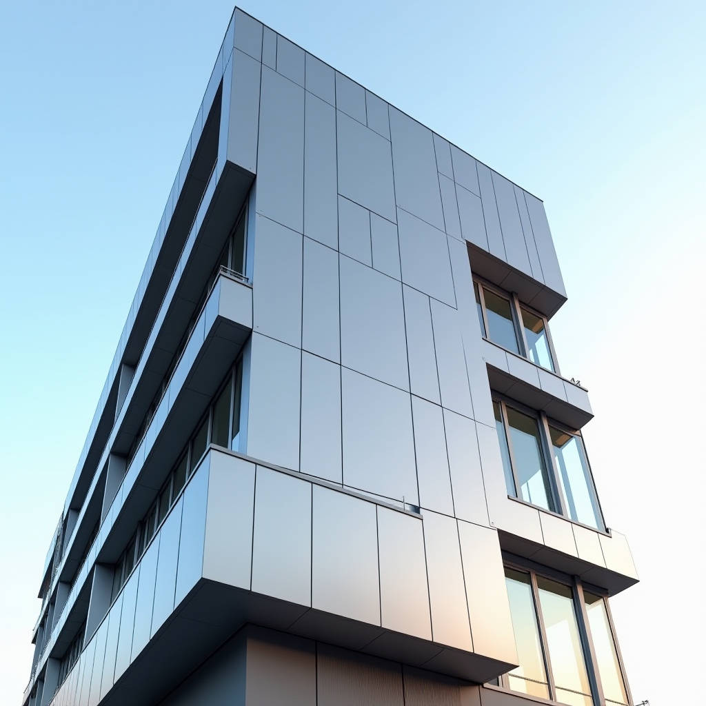
The Tray Aluminum Panel System sits at the centre of modern rainscreen facade engineering, yet its real value is often buried under glossy marketing. For a building envelope contractor or international procurement manager, the difference between a well-specified tray panel facade and a poorly detailed one shows up years later in water ingress claims, thermal bridging audits, and maintenance budgets. This article breaks down the Tray Aluminum Panel System from a structural and specification standpoint: how the drained and ventilated cavity actually works, how to size the extruded aluminium grid and brackets, and which coating and fire classifications matter when you are writing a performance specification for a solid aluminium panel project. We will work through load paths, drainage tolerances, and the practical numbers that keep a 2.0 mm to 3.0 mm solid aluminium tray panel system performing for decades.
Why the Drained and Ventilated Cavity Defines the System
The defining feature of a Tray Aluminum Panel System is not the visible panel face but the open cavity behind it. A correctly detailed system allows air to enter at the base of the elevation and exit at the top, which drives two separate mechanisms. First, the moving air equalises pressure across the cavity, so wind-driven rain is far less likely to be forced through joints. Second, the ventilation path evacuates moisture vapour that migrates from the interior, preventing condensation from pooling against the insulation or the back of the panels.
This is a fully drained and ventilated facade, not a sealed cladding. The panels act as the outer weather screen, while the extruded aluminium grid provides the structural support plane. The cavity depth is a design decision, not an accident. A typical ventilated cavity sits between 20 mm and 50 mm, depending on the substrate, insulation thickness, and the acoustic or thermal strategy of the wall build-up. Shallow cavities risk capillary bridging at the joints; excessively deep cavities add bracket cost without meaningful performance gain.
Structural Load Path and the Extruded Aluminium Grid
Every load on a tray panel facade travels through the same chain: the solid aluminium panel, the fixing brackets, the support rails, and finally the structural substrate. Understanding this path is the first step to a safe specification. The panel itself is typically 2.0 mm, 2.5 mm, or 3.0 mm solid aluminium sheet, folded into a tray profile with return edges. The returns add stiffness that a flat sheet of the same gauge cannot match, which is why tray panels can span larger grid zones than a flat cassette of equal thickness.
The extruded aluminium grid is the heart of the system. It offers a variety of zone widths, meaning the designer can tune the module to the facade geometry rather than forcing the architecture to fit a fixed panel size. The grid also provides excellent adjustability, which is critical on real construction sites where the concrete or steel substrate is rarely perfectly true. Slotted holes in the brackets and rails allow for in-plane and out-of-plane adjustment, so the finished facade plane can be set to a tight tolerance even when the substrate wanders.
For wind load calculations, the governing figure is the net pressure coefficient for the specific building zone, combined with the local terrain category and height. As a working estimate, a mid-rise building in an urban terrain with a 40 m height may see a design wind pressure in the range of 1.2 to 1.8 kPa on the worst corner zones. The bracket spacing and rail gauge must be checked against this pressure using the manufacturer's tested capacities. A common bracket spacing is 600 mm vertically, with rails spanning between brackets, but this must be verified against the actual load case, never assumed.
Fire Classification and Material Compliance
Fire performance is a non-negotiable line item in any international specification. The tray panel system can be supplied with materials classified as A1 or A2 under BS EN 13501-1:2018, depending on the specification. This is a decisive advantage of a solid aluminium tray panel over composite alternatives, because the core of a solid aluminium sheet carries no combustible content. The distinction matters for building codes that restrict combustible cladding on high-rise structures.
When you specify the system, confirm the reaction-to-fire classification of every component, not just the panel. The extruded aluminium grid, the gaskets, and any thermal break material must all fall within the same fire strategy. A facade is only as fire-safe as its weakest component, and a combustible gasket can undermine an otherwise non-combustible assembly. For projects governed by the European Construction Products Regulation, the Declaration of Performance should be requested and reviewed before award.
Coating Systems and Weathering Performance
The durability of a Tray Aluminum Panel System hinges on the coating. For architectural exterior use, a two-coat or three-coat PVDF (polyvinylidene fluoride) system is the industry benchmark. The total dry film thickness for a quality PVDF finish is typically 25 to 30 microns for the two-coat system and up to 40 microns for a three-coat system with a primer and clear coat. This film thickness is what delivers the 20-year-plus weathering warranties that international clients expect.
The table below compares the coating options you will encounter when specifying a solid aluminium tray panel facade.
| Coating Type | Typical DFT (microns) | Gloss Retention | Colour Range | Best Application |
|---|---|---|---|---|
| Two-coat PVDF | 25-30 | Good, 5-10 year warranty | Full RAL range | Cost-sensitive commercial facades |
| Three-coat PVDF | 35-40 | Excellent, 20+ year warranty | Full RAL plus metallic | Premium and high-rise projects |
| Polyester (PE) | 20-25 | Moderate, fading over time | Standard colours | Interior or short-life applications |
| Anodised (natural) | 15-25 oxide layer | Very high, no fading | Silver/bronze tones | Architectural metallic aesthetics |
For coastal or industrial atmospheres, the three-coat PVDF system is the safer engineering choice. Salt spray and airborne pollutants attack the film edge at cut edges and drilled holes, so the coating warranty is only as good as the edge treatment. Specify that all cut edges, slots, and drilled holes receive a touch-up or edge sealant to protect the exposed aluminium from corrosion. This is a detail that is easy to overlook in the shop drawing phase and expensive to fix after installation.
Drainage, Ventilation, and Joint Design
A tray panel system is designed to drain water, not to hold it. The horizontal joints should be detailed with a drip edge or stepped profile so that water runs off the panel face rather than being wicked back into the cavity. Vertical joints are typically open or gasketed, depending on the aesthetic and the wind-driven rain exposure of the site. Open joints rely on the pressure-equalised cavity to keep water out, while gasketed joints provide a more positive seal at the cost of slightly reduced ventilation.
The maximum gap width is a specification point that must be stated. Some tray systems are designed for a maximum horizontal and vertical gap width of 20 mm, which is a practical upper limit for a pressure-equalised joint. Wider gaps increase the risk of water ingress and reduce the visual tightness of the facade. The panels are often fixed at the upper edge to vertical hat-section supports using stainless steel fixings, which allows the panel to hang and drain naturally while accommodating thermal movement.
Thermal movement is a real force in a solid aluminium panel. Aluminium expands at roughly 23 x 10-6 per degree Celsius, so a 3 m panel spanning a 60 degree Celsius temperature swing can move around 4 mm. The joint design and fixing method must absorb this movement without transferring stress to the brackets or causing the panel to buckle. Slotted fixings and flexible gaskets are the standard answer, and the shop drawings should show the movement allowance explicitly.
Corrosion Strategy and Fixings
The support structure of a quality Tray Aluminum Panel System uses aluminium helping-hand brackets and support rails fixed with stainless steel self-drive screws. These stainless steel fixings do not corrode, even under extreme atmospheric conditions, which is essential because a galvanic reaction between the aluminium panel and a ferrous fixing would rapidly destroy the panel edge. The choice of stainless steel grade matters; A2 (304) is standard for most environments, while A4 (316) is preferred for coastal or aggressive industrial sites.
Dissimilar metal contact is the most common premature failure mode in metal facades. Where the aluminium panel meets a stainless steel bracket, the contact is generally acceptable because both are passive metals. But where aluminium meets carbon steel, copper, or brass, an isolation barrier is required. Specify a nylon or EPDM isolation washer and sleeve at every contact point, and verify this in the shop drawings. This is a low-cost detail that prevents a high-cost failure.
Bespoke Configurations and Integration
The tray panel format is not limited to flat rainscreen cladding. The same structural logic adapts to louvre backing panels, where the tray panel sits behind an aluminium louvre blade to provide a weather screen or acoustic barrier. These backing panels can be supplied in single-skin, insulated, or tray panel formats, with cut-outs for services and plenum box options to suit bespoke requirements. This integration is common in plant rooms, mechanical floors, and high-rise service zones where the facade must hide equipment while maintaining a clean exterior line.
When a project requires a mix of rainscreen panels and louvre backing, it is worth engaging a supplier early in the design phase. A manufacturer with in-house engineering can reconcile the grid module, the panel tolerances, and the fixings across both systems, so the construction team does not inherit a coordination problem on site. For procurement managers, this early engagement also locks in the supply chain and avoids the premium pricing that comes with last-minute changes.
Installation Tolerances and Site Practice
The fastest way to ruin a well-engineered tray panel facade is poor site practice. The grid must be set out and surveyed before the first panel is hung, and the vertical and horizontal datums should be checked against the structural grid, not against the previous panel. A common tolerance is +/- 3 mm in the panel plane and +/- 2 mm in the joint width, but this should be written into the quality plan and enforced with a survey hold point.
Panels are installed using a tongue-and-groove or similar interlocking method, which speeds up installation compared to a fully gasketed system. The interlock provides a positive alignment between adjacent panels, reducing the reliance on the installer's eye for joint consistency. For a large facade, this translates directly into labour savings, which is why the tray panel format is a strong value proposition for cost-conscious contractors.
For a reliable supply of solid aluminium tray panels with verified coating and fire documentation, a manufacturer such as Futeng® can provide the engineering support and production capacity that international projects demand. The key is to select a partner who will share test data and shop-drawing support, not just a price list.
Engineering Recommendations for Specification
When you write the specification for a Tray Aluminum Panel System, anchor every decision to a measurable performance requirement. Start with the design wind pressure for the building zone, then size the grid and brackets against that load. Confirm the reaction-to-fire classification of every component against the governing building code. Select a three-coat PVDF system for exterior exposure and specify edge protection for all cut faces. Detail the drainage and ventilation cavity with a stated depth and a maximum joint gap, and mandate stainless steel fixings with isolation washers at every dissimilar metal contact.
Finally, verify the manufacturer's test evidence against the relevant standards. Cross-reference the coating performance with AAMA 2605 for high-performance organic coatings, the fire classification with BS EN 13501-1, and the overall facade performance with the guidance from the Centre for Window and Cladding Technology (CWCT). These references give your specification a defensible technical foundation that will survive value engineering and site queries. A tray panel facade specified this way will drain, ventilate, and perform for decades, which is the only outcome that matters for the building owner and the contractor's reputation.