Interlocking Aluminum Panel System Engineering for Wind Load and Joint Durability in Facades
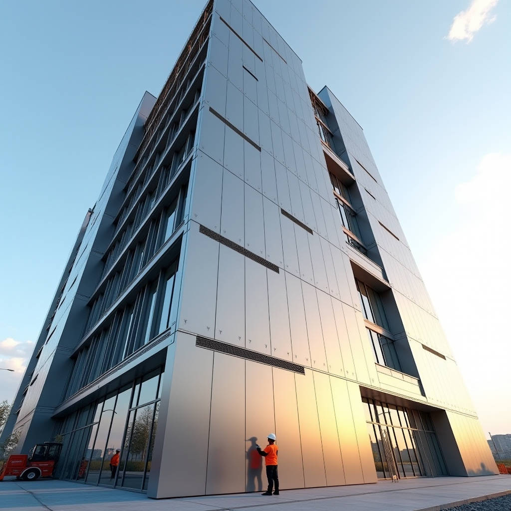
An Interlocking Aluminum Panel System differs from conventional screw-fixed or wet-sealed cladding in one decisive way: the finished facade no longer depends on a continuous bead of sealant or a line of exposed fasteners to stay watertight. Instead, factory-formed male and female edges engage mechanically, transferring wind load through the joint and letting each panel expand and contract independently. For facade contractors bidding on rainscreen work, this changes the cost model, the sequencing, and the long-term maintenance liability. This article examines the structural behavior of dual-axis interlocking joints, the engineering values that drive panel gauge selection, and the coating and testing criteria that separate a durable assembly from a warranty claim waiting to happen.
Why Interlocking Beats Conventional Dry Joints
Traditional dry-joint rainscreens rely on open gaps and a pressure-equalized cavity to shed water. Interlocking panels take a different route. The joint itself is a labyrinth that blocks driven rain while still venting the cavity. Because the interlock is machined at the factory, every panel edge is identical, which removes the single largest variable on site: the skill of the installer applying sealant. NorthClad's AL-DI series, which interlocks both horizontally and vertically, is a practical reference for how this geometry behaves in a vented rainscreen, and its documentation shows the system exceeds standard wind-driven rain testing without butyl tape or sealant.
For a contractor, the immediate benefit is schedule. A dual-interlocking panel locks in place on two axes, so the crew does not wait for a sealant cure cycle before moving to the next bay. On a 20,000 m² facade, eliminating sealant cure time can compress the cladding program by several weeks. The mechanical joint also tolerates thermal movement far better than a rigid adhesive bond. Solid aluminum at 3.0 mm gauge moves roughly 0.024 mm per meter per 10 °C of temperature swing. Over a 4 m panel, a 50 °C swing means about 4.8 mm of movement that the joint must absorb without transferring stress to the substrate.
Dual-Axis Interlocking and Structural Load Paths
The critical engineering question is how the interlock carries wind load. In a single-axis system, the horizontal joint carries most of the suction load and the vertical joint is largely decorative. A dual-interlocking profile distributes load across both axes, which reduces the peak stress at any single engagement point. This matters in high-wind zones where the design wind pressure can exceed 2.5 kPa. The load path runs from the panel face through the interlock into the supporting clip, then into the subframe. The clip spacing is the real design variable, not the panel thickness alone.
For a typical 2.0 mm solid aluminum panel, a clip spacing of 600 mm on center handles most low-rise conditions. At 3.0 mm gauge, the same spacing supports higher wind zones and larger panel modules. The table below summarizes realistic engineering guidance for a dual-interlocking solid aluminum panel system.
| Panel Gauge (mm) | Max Panel Module (m) | Design Wind Load (kPa) | Clip Spacing (mm) | Typical Application |
|---|---|---|---|---|
| 2.0 | 1.2 × 3.0 | 1.5 | 600 | Low-rise, sheltered |
| 2.5 | 1.5 × 3.6 | 2.0 | 500 | Mid-rise, urban |
| 3.0 | 1.8 × 4.0 | 2.5 | 400 | High-rise, coastal |
| 3.0 | 1.8 × 4.0 | 3.0+ | 300 | Hurricane-prone |
These figures assume a vented cavity, a rigid subframe, and a panel alloy in the 5000 series with a yield strength near 190 MPa. They are starting points for a structural engineer's calculation, not substitutes for it. The interlock geometry itself must be verified against the AAMA 508 pressure-equalized rainscreen test method, which measures water penetration under dynamic wind pressure.
Coating Systems That Survive the Joint
The interlock is a cold-formed bend, and the coating at the bend radius is where most premature failures begin. A coating that cracks at the bend exposes the aluminum to edge corrosion, and once corrosion starts at the joint it migrates under the film. The standard for architectural aluminum is a 70% PVDF coating applied at a minimum dry film thickness of 25 microns over a corrosion-resistant primer. The film must survive a 2T bend test without cracking, which is why the coating specification matters as much as the alloy.
For coastal projects, the spec should require a primer with a chromate-free conversion coating and a topcoat meeting the ASTM B117 salt spray requirement of at least 4,000 hours without blistering or creep from the scribe. Interior and ceiling applications, where UV exposure is minimal, can use a polyester coating at a lower cost, but the interlock still needs the same bend flexibility. The coating is not decorative; it is the corrosion barrier for the most stressed part of the panel.
Installation Sequencing and Tolerance Control
Interlocking panels punish sloppy subframe work. Because the panels lock together, a subframe that is out of tolerance by even 5 mm will show up as a visible step at every joint. The installation sequence should start with a laser-verified subframe, then hang panels from the bottom up so each panel's weight rests on the interlock below it rather than hanging from the clip above. This bottom-up approach also lets the crew check the joint fit as they go, catching a bowed panel before it is locked into a row of five.
Standoff clips give the installer a way to correct minor out-of-plane deviations without shimming the whole frame. The clip also creates the air gap that makes the system a true rainscreen, so the cavity stays open and the drainage path is continuous. A common mistake is to caulk the interlock joints thinking it adds waterproofing. It does not help and it blocks the cavity ventilation that dries the assembly. The interlock is designed to be dry; sealant only belongs at penetrations and terminations.
Specifying for Wet, Frost, and Fire-Prone Zones
Interlocking systems earn their keep in climates where sealant fails. In freeze-thaw zones, a wet-sealed joint expands and contracts until the sealant tears, then water enters and the cycle accelerates. The mechanical interlock has no sealant to tear. Knotwood's interlocking boards, which are rated for wet, frost, and fire-prone areas, illustrate the same principle applied to a residential-scale product. The principle transfers directly to commercial solid aluminum panels: the joint is the weather barrier, so the material and the geometry carry the responsibility that sealant carries in a conventional system.
For fire-prone zones, the solid aluminum panel itself is non-combustible, and the interlock eliminates the combustible sealant bead that a wet-sealed system would leave in the joint. This can simplify compliance with local fire codes and with the NFPA 285 exterior wall assembly test, because there is no continuous sealant line to propagate flame. The cavity still needs fire-stopping at floor lines, but the interlock removes one failure path from the assembly.
Cost Reality Check for Procurement
An interlocking panel costs more per square meter than a flat panel with exposed fasteners, because the edge machining and the CNC fabrication add labor. The offset is in installation labor, which is lower because the crew does not seal, set, and cure every joint. For a 10,000 m² project, the labor saving typically offsets the material premium within the cladding package, and the maintenance saving over a 25-year service life is where the real return sits. A wet-sealed facade needs re-caulking every 8 to 12 years; an interlocking facade does not.
When sourcing, the buyer should ask for the CNC tolerance certificate, the coating bend-test report, and the AAMA 508 test data for the exact profile being quoted. A supplier that cannot produce these documents is quoting a different product than the one that will be installed. Futeng® builds solid aluminum interlocking panels to these documented standards and can supply the test reports alongside the fabrication drawings, which keeps the procurement and the engineering review on the same page.
Engineering Guidance for the Facade Team
Decide the design wind load first, then let it drive the gauge and clip spacing. Do not let aesthetics pick the panel module before the structural calculation is done. Specify the coating bend test and salt spray requirement in the contract documents, not as an afterthought. Sequence the work bottom-up, verify the subframe with a laser, and keep the cavity open. On the maintenance side, budget for periodic inspection of the terminations and penetrations, because those are the only places water can still enter. The interlock handles the field; the details handle the edges.
An interlocking aluminum panel system is not a magic fix for a bad subframe or a rushed schedule. It is a disciplined assembly that rewards factories that hold tolerance and contractors who respect the sequence. When the engineering values are set correctly and the coating is specified for the real environment, the system delivers a facade that sheds water, breathes, and moves thermally without asking for maintenance every decade. That is the value a procurement team should be buying, and the test data should prove it before the first panel ships.