Lay In Aluminum Panel System Engineering for Durable Serviceable Ceilings
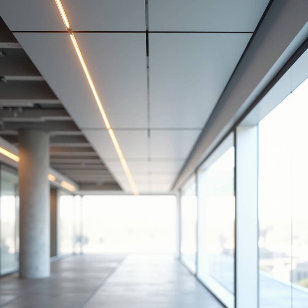
The Lay In Aluminum Panel System has moved well beyond the suspended office ceiling it is best known for. Contractors now specify solid aluminium lay-in panels for exterior rainscreen cladding, corridor ceilings, transit stations, and cleanroom environments where access to services above the plane is a daily requirement. The defining trait of this system is simple: panels rest on the flanges of an exposed T-grid, so any single tile can be lifted out without disturbing its neighbours. That access advantage drives maintenance schedules, fire-rated plenum strategies, and acoustic performance in ways a fixed cassette system cannot match. This article examines the engineering decisions that separate a durable solid aluminium lay-in installation from a problematic one, with emphasis on panel thickness, edge geometry, coating specification, and load calculations for the supporting grid.
Why Solid Aluminium Beats Composite in a Lay-In Grid
The Lay In Aluminum Panel System is frequently specified with solid aluminium sheet rather than composite panels, and the reasons are structural. A solid 2.0mm or 2.5mm panel carries its own stiffness across a 600mm or 1200mm grid module without the buckling risk that thin-skinned composite faces introduce at the edges. When a maintenance worker kneels on a tile to reach a valve above the plenum, the solid sheet distributes the point load across the grid flange. Composite panels, with their polyethylene core, deform permanently under the same load and lose their flatness. Solid aluminium also delivers a clean, square cut edge that seats flush on the tee flange, which matters when the grid is exposed as a deliberate design feature rather than hidden above a gypsum border.
Edge Geometry and Panel Sizing
Every Lay In Aluminum Panel System relies on the interaction between the panel edge and the suspension tee. Three edge profiles dominate commercial specification: square, reveal, and flush. The square edge sits directly on the flange and produces a crisp 15mm or 24mm grid line. The reveal edge incorporates a small step that creates a shadow line, softening the visual grid. The flush edge drops the panel face level with the tee, producing a near-continuous surface that reads as a monolithic ceiling. Panel sizes follow the grid module, with 600mm x 600mm and 600mm x 1200mm the most common in metric markets, and 2 x 2 feet and 2 x 4 feet in imperial markets. For solid aluminium, the practical maximum span across a 1200mm module is limited by deflection under self-weight and maintenance loads. A 2.0mm panel over a 1200mm span will deflect noticeably under a concentrated load, so specifiers should either reduce the module to 600mm or increase thickness to 2.5mm when large-format solid panels are required.
Load Path and Grid Capacity
The grid is the load-bearing element, not the panel. Standard main tees and cross tees are rated by the manufacturer for a specific dead load and deflection limit. When a Lay In Aluminum Panel System uses solid aluminium at 2.5mm thickness, the panel weight approaches 6.75 kg per square metre. Across a 600mm x 600mm module, that is roughly 2.4 kg per tile, well within the capacity of a standard 15/16 inch tee. The more demanding calculation is the concentrated maintenance load. Industry practice, following the guidance in ASTM C635 and C636, assumes a 90 kg point load applied to the centre of a single panel during servicing. The grid must be designed so that the supporting tee and its hanger wires carry this load without exceeding the deflection limit of 1/360 of the span. Hanger wire spacing should be reduced to 1200mm along the main tees in high-access areas, and hold-down clips become mandatory in any installation where wind uplift or negative pressure can act on the panels, such as exterior soffits or ventilated facades.
Coating and Corrosion Specification
The service life of a Lay In Aluminum Panel System depends almost entirely on the coating system. For interior ceilings, a polyester powder coating at 60 to 80 microns provides adequate durability and a wide colour range. For exterior rainscreen applications or humid environments, specifiers should step up to a two-coat PVDF system at 25 to 30 microns total dry film thickness, or a three-coat system where the substrate is exposed to coastal salt. The four-step pretreatment and coating process used by leading manufacturers, as documented in the AAMA 2605 specification for exterior architectural coatings, delivers superior paint adherence and corrosion resistance. Interior panels can be specified to AAMA 2604, while exterior solid aluminium panels should meet AAMA 2605. Perforated panels add a further consideration: the cut edges of the perforations expose bare aluminium, so the coating must be applied after perforation or the edges must be treated to prevent white rust formation in humid plenums.
Acoustic Performance of Perforated Solid Panels
Acoustic control is a primary reason architects choose a Lay In Aluminum Panel System over a flat gypsum ceiling. Perforated solid aluminium panels, backed with a non-woven acoustic fleece or a mineral wool batt laid in the plenum, convert the ceiling into a sound-absorbing surface. The noise reduction coefficient depends on the perforation pattern, the open area percentage, and the depth of the airspace behind the panel. A 23% open area pattern with a 50mm mineral wool backing typically achieves an NRC of 0.85 to 0.95. The acoustic fleece must be factory-bonded to the back of the solid panel, not field-applied, because field-applied fleece delaminates and sags within years. For cleanrooms and healthcare environments, the antibacterial coating option described in the four-step process used by USG ME provides a surface that resists microbial growth on the exposed aluminium face.
Installation Sequence and Access Strategy
Installation of a Lay In Aluminum Panel System follows a predictable sequence that rewards careful planning. The suspension grid is laid out first, with hanger wires fixed to the structural slab at the specified spacing. The main tees are installed at the module spacing, and cross tees are snapped into place to form the grid. Panels are then laid in from above, resting on the flanges. The critical planning decision is the service access strategy. Where panels sit above active mechanical or electrical services, the ceiling layout should mark which tiles are designated access points. A dedicated access tile, slightly smaller than the standard module to allow finger clearance, prevents damage to the surrounding panels during repeated removal. Hold-down clips are fitted to panels in wind-exposed locations or where positive pressure from a plenum HVAC system could lift a tile.
Cost and Productivity Comparison
For a procurement manager evaluating ceiling systems, the installed cost of a solid aluminium lay-in system is competitive with fixed cassette systems when labour is factored in. The following table compares typical installed costs and productivity across three common approaches for a 1000 square metre interior ceiling.
| System | Panel Thickness | Grid Type | Installed Cost (USD/m²) | Productivity (m²/crew/day) | Access to Plenum |
|---|---|---|---|---|---|
| Solid Aluminium Lay-In | 2.0mm | Exposed 15mm tee | 85–110 | 120–150 | Full, individual tile |
| Solid Aluminium Fixed Cassette | 2.0mm | Concealed | 110–140 | 70–90 | Limited, screw removal |
| Gypsum Board on Metal Stud | 12.5mm | None | 55–75 | 40–60 | None without demolition |
The productivity advantage of the lay-in method is substantial. Because panels drop in from above without fasteners, a two-person crew can install 120 to 150 square metres per day, roughly double the rate of a concealed cassette system. The trade-off is the exposed grid line, which not every design accepts. Where the grid is acceptable, the access benefit compounds over the building life: every service call above the ceiling avoids the cost of cutting and patching gypsum.
Fire Performance and Plenum Compliance
Solid aluminium panels carry a distinct advantage in fire-rated plenum assemblies. Aluminium is non-combustible, and a solid 2.0mm panel will not contribute fuel to a fire. The grid and hanger system must still meet the local fire code, and the plenum space must comply with the relevant standard for smoke and flame spread. The panels themselves, when tested to ASTM E84, typically achieve a Class A rating with a flame spread index below 25 and a smoke-developed index below 50. For projects requiring a fire-resistance rating for the ceiling assembly, the lay-in system can be combined with a fire-rated board above the grid, with the solid aluminium panels acting as the exposed finish. This two-layer approach preserves the access benefit while meeting the rating, a combination that concealed systems struggle to match.
Environmental and Lifecycle Considerations
Aluminium is infinitely recyclable, and a solid panel retains its value at end of life. The coating system, however, determines whether the panel can be recycled directly or must be processed. PVDF and powder coatings are removed during the remelting process, so coated panels are recyclable through standard aluminium scrap channels. The energy embodied in a 2.0mm solid aluminium panel is offset by the material's durability: a correctly coated panel with a PVDF finish will last 40 years or more in an interior application, and 25 to 30 years in an exterior rainscreen. The ISO 14040 lifecycle assessment framework provides the methodology for quantifying this benefit, and several green building rating systems award credits for the recycled content and the access-based maintenance savings.
Specification Checklist for Procurement
When writing a specification for a Lay In Aluminum Panel System, the procurement team should lock down several parameters before tender. Panel thickness should be stated as 2.0mm minimum for standard modules, rising to 2.5mm for 1200mm spans or exterior use. The aluminium alloy should be specified as 1100 or 3003 series, with 3003 preferred where higher strength is required. The coating system must be named with its total dry film thickness and the applicable AAMA standard. Perforation patterns, if required, should be defined by open area percentage and hole diameter, with the acoustic fleece specified as factory-bonded. Finally, the grid system should be named by brand and model, with hanger spacing and hold-down clip requirements stated. A reliable supplier such as Futeng® can provide documented coating test data and deflection calculations to support the specification, and their production capacity for solid aluminium panels in 2.0 to 3.0mm thickness is a practical reference point for large projects.
Conclusion
The Lay In Aluminum Panel System remains the most serviceable ceiling and soffit solution available to the contractor, provided the engineering fundamentals are respected. Solid aluminium panels at 2.0mm or 2.5mm thickness, specified with the correct edge profile, coating system, and grid capacity, deliver a durable and accessible surface that outperforms composite alternatives under maintenance loads. The exposed grid is a design decision, not a compromise, and the access advantage it provides pays dividends over the full building life. For exterior or high-humidity applications, specify PVDF to AAMA 2605, add hold-down clips, and verify the grid's concentrated load capacity. With these parameters locked in, the lay-in system is a dependable, cost-effective choice for commercial, institutional, and industrial projects.