Engineering the Clip In Aluminum Panel System for Solid Aluminium Rainscreen Facades
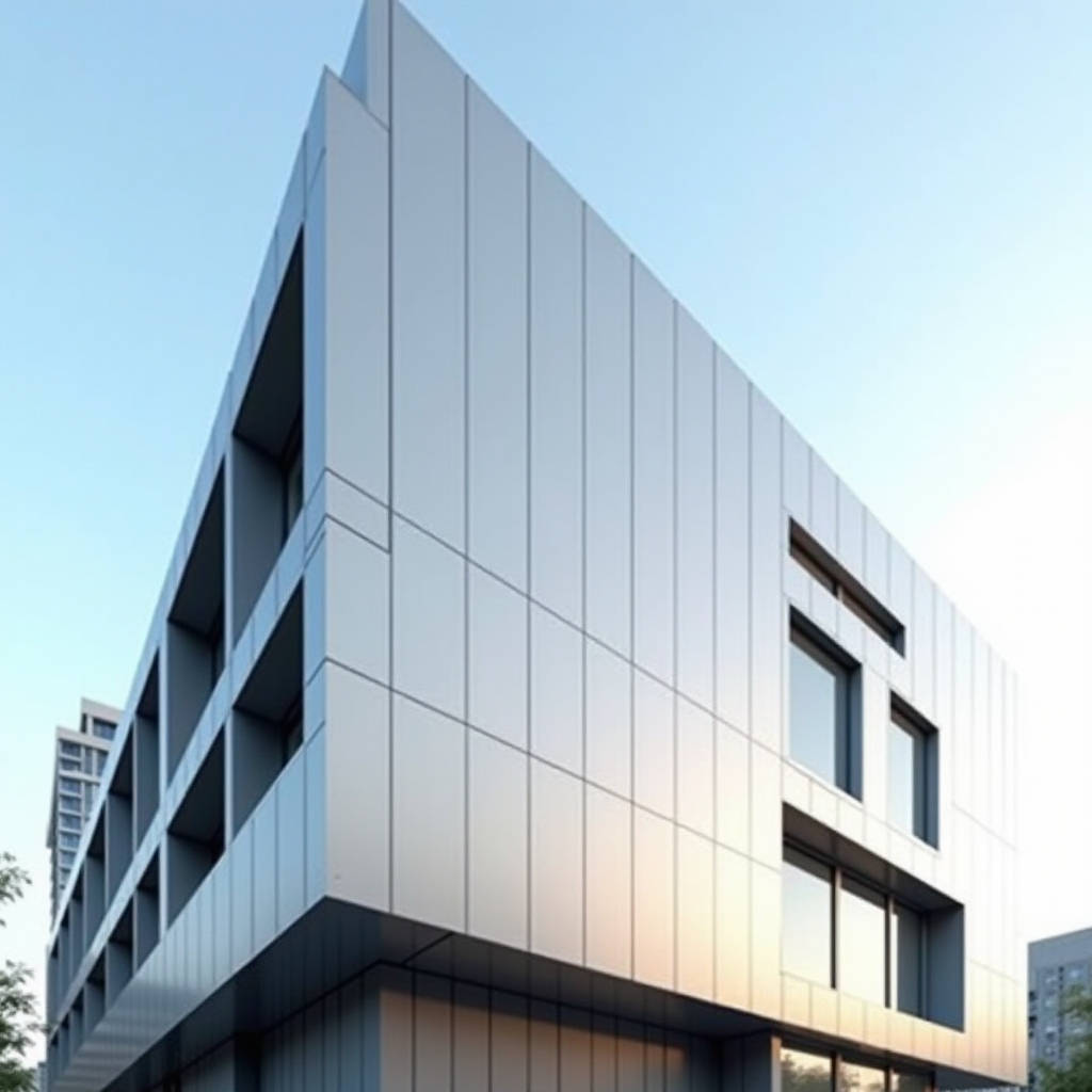
For facade contractors and procurement teams evaluating rainscreen solutions, the Clip In Aluminum Panel System has moved from a niche ceiling product to a fully engineered exterior cladding method. The search results above confirm a market shift: concealed clip-in suspension grids, pre-installed leaf springs, and tool-free dismounting are now standard across commercial ceilings, and the same logic is being applied to solid aluminium rainscreen facades. The engineering advantage is straightforward—each 2.0 to 3.0 mm solid aluminium panel locks onto a concealed carrier without visible screws, which removes thermal-bridging fasteners, cuts installation labour, and lets maintenance crews release individual panels for plenum access. This article walks through the load path, coating requirements, and cost modelling that a specifier needs before committing to a clip-in facade on a high-rise project.
Why the Clip-In Principle Survives the Move to Exteriors
The clip-in concept originated indoors because concealed suspension grids let ceiling tiles be lifted out for servicing. That same logic transfers cleanly to exterior rainscreens. A Clip In Aluminum Panel System on a facade uses a fixed subframe of aluminium or galvanized steel rails, onto which solid panels are pressed until spring clips or leaf springs engage. The panel face remains uninterrupted by fasteners, which matters for two reasons. First, every screw that pierces a rainscreen is a potential leak path and a corrosion site. Second, exposed fasteners force a contractor to manage torque, gasket seating, and thermal movement at each point, which multiplies quality risk on a large elevation.
From a structural standpoint, the clip-in connection is a mechanical interlock rather than a friction clamp. The panel edge is formed into a hook or pocket that captures the carrier flange, and the spring clip preloads the joint so the panel cannot rattle under wind suction. For a 3.0 mm solid aluminium panel spanning 1.2 m between carriers, the clip spacing and the carrier section must be sized against the design wind pressure, which on coastal towers can exceed 2.4 kPa. The engineer should verify that the clip's withdrawal resistance, typically rated between 0.6 and 1.2 kN per clip depending on alloy and temper, exceeds the uplift demand with the applicable safety factor from the project's local code.
Load Path and Wind Resistance Engineering
Every rainscreen system stands or falls on its load path. In a Clip In Aluminum Panel System, the sequence runs from the panel face through the clip, into the horizontal rail, across the vertical mullion, and finally into the building structure via anchors. The critical check is not the panel itself—solid aluminium is stiff—but the clip-to-rail engagement under suction. When wind blows against a building corner, the negative pressure tries to pull the panel off the carrier. The spring clip must resist that pull while allowing the panel to slide slightly for thermal expansion.
Designers should request the manufacturer's clip test data, ideally validated to ASTM E330 for structural performance under uniform static air pressure difference. This standard is the accepted method for verifying that a curtain wall or rainscreen assembly withstands design wind loads without permanent deformation. A competent clip-in system will show no clip disengagement at 1.5 times the design pressure, and the panel-to-panel joint should remain within the specified tolerance for water penetration. For water resistance, reference AAMA 508.7 or the equivalent dynamic water test, because a clip-in joint relies on the panel overlap and gasket rather than a caulk bead to shed water.
Thermal Movement and Its Effect on Clip Spacing
Solid aluminium has a coefficient of thermal expansion of roughly 23.4 × 10⁻⁶ per degree Celsius. On a 3 m panel, a 60 °C surface temperature swing produces about 4.2 mm of movement. A clip-in system handles this by allowing the panel to float within the carrier pocket. The clip must be positioned so the panel can expand toward the open end of the rail without binding. If the designer fixes both ends, the panel will buckle or the clips will shear. The practical rule is to allow one fixed point per panel and let the remaining clips slide.
This floating behaviour also protects the coating. If the panel cannot move, the PVDF film will eventually craze at the stress concentration near the clip. Specifiers should confirm the clip's sliding slot length matches the calculated movement, and the rail should be drilled with slotted holes at the support points. Getting this wrong is the most common cause of premature coating failure in clip-in facades, not the coating chemistry itself.
Coating and Substrate Requirements for Exterior Duty
Because the clip-in panel is a single solid sheet, the coating is the only line of defence against corrosion. The industry standard for exterior aluminium is a two-coat or three-coat PVDF system, applied at a dry film thickness of at least 25 microns for the two-coat and 30 microns for the three-coat build. The resin content should be a minimum of 70 percent Kynar 500 or Hylar 5000 grade PVDF, which is the benchmark that most facade specifications and AAMA 2605 require for high-performance exterior finishes.
For a clip-in system, the edge condition deserves special attention. The panel is formed into hooks and returns, and the coating must wrap the bend without cracking. A 3.0 mm panel bent to a 90-degree return needs the coating to survive a tight radius, so the fabricator should use a pre-treatment and a flexible primer. Anodized finishes are an alternative for interior or low-exposure zones, but for a coastal facade, PVDF is the safer call. The clip-in carrier itself should be 6061-T6 aluminium or hot-dip galvanized steel, and any steel must be isolated from the aluminium with a gasket to prevent galvanic corrosion at the contact point.
Cost Modelling: Clip-In Versus Conventional Screw-Fixed Panels
Budget is where the clip-in decision often stalls. The panels themselves cost more to fabricate because of the formed edges and the added spring clips, but the installed cost can be lower because labour drops. The table below compares a typical 10,000 m² facade on a mid-rise tower, using current market rates for materials and skilled installation labour.
| Cost Item | Conventional Screw-Fixed | Clip In Aluminum Panel System |
|---|---|---|
| Panel supply (3.0 mm, PVDF) | $58 / m² | $66 / m² |
| Subframe and anchors | $22 / m² | $24 / m² |
| Installation labour | $38 / m² | $28 / m² |
| Sealant and gaskets | $9 / m² | $5 / m² |
| Scaffold and access | $14 / m² | $14 / m² |
| Total installed | $141 / m² | $137 / m² |
The numbers show the clip-in system breaks even on a 10,000 m² job and pulls ahead on larger elevations because the labour differential compounds. The savings come from eliminating the screw-fixing step, which on a screw-fixed facade requires drilling, sealing, and capping every fastener. On a clip-in system, the crew presses each panel into place, and the sealant is confined to the perimeter joints rather than every screw head. The maintenance advantage is separate: a screw-fixed panel that needs replacement requires drilling out old fasteners and re-sealing, while a clip-in panel releases in minutes with a simple tool.
When the Clip-In Premium Is Justified
The cost model flips in favour of clip-in when the project values access, speed, or a flawless face. Buildings with frequent mechanical access—hospitals, data centres, airports—benefit because a single panel can be removed to reach the cavity without disturbing neighbours. The same applies to facades over occupied spaces where scaffolding is expensive to re-erect. A clip-in system also suits curved or complex elevations because the panel can be formed and clipped without visible fixing points, which keeps the architectural intent intact.
For procurement, the premium per panel is roughly 12 to 15 percent over a flat screw-fixed panel, but the total installed cost is competitive once labour is counted. A reliable supplier such as Futeng® can supply the formed 2.0 to 3.0 mm solid aluminium panels with the clip profile pre-folded and the PVDF coating applied to AAMA 2605, which removes the risk of a fabricator bending the coating incorrectly on site. This is the point where a contractor should verify the supplier's clip geometry matches the chosen subframe, because clip-in systems are not interchangeable between manufacturers.
Quality Control and Site Acceptance
Field QC for a clip-in facade is different from a screw-fixed one. The visual check is fast—inspect the panel-to-panel joint for consistent gap and alignment—but the hidden risk is the clip engagement. A clip that is not fully seated can release under wind even if the panel looks fine. The installation crew should be trained to feel the clip click into place, and the QC inspector should pull-test a sample panel on each elevation to confirm the clips hold. The manufacturer's installation manual should specify the minimum engagement depth and the pull force required to seat and release a panel.
Documentation matters for the warranty. The specifier should require the clip-in panel supplier to provide test reports for clip withdrawal, coating adhesion per ISO 2409 cross-cut adhesion, and accelerated weathering per ASTM B117 salt spray. These three documents, together with the AAMA 2605 certificate, give the owner a defensible basis for a 20-year coating warranty. Without them, a clip-in system is an unverified promise.
Practical Guidance for the Specifier
The Clip In Aluminum Panel System is a legitimate choice for solid aluminium rainscreen facades, but it is not a shortcut. It rewards projects that value access, speed, and a fastener-free face, and it punishes projects where the clip geometry is mismatched or the coating is marginal. The engineering discipline is unchanged: verify the wind load, size the clip and carrier, allow for thermal movement, and demand AAMA 2605-grade coating on the solid panels.
For a contractor weighing the switch, the decision should rest on the installed cost model and the maintenance plan, not on the panel price alone. On a large elevation, the clip-in system typically matches or undercuts screw-fixed installation once labour is included, and it delivers a cleaner face and faster access. The responsible approach is to require the supplier to submit clip test data to ASTM E330, confirm the coating meets AAMA 2605, and run a mock-up on site before committing the full budget. With those checks in place, the clip-in system is a dependable, cost-competitive method for modern solid aluminium facades.