Aluminum Facade Installation Engineering Guide for Durable Solid Panel Envelopes
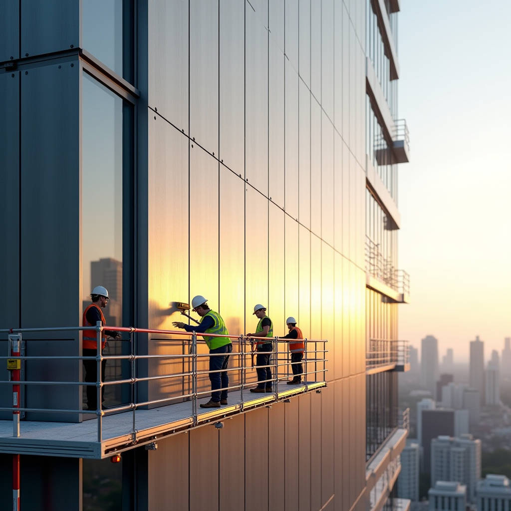
Aluminum Facade Installation is judged by what happens behind the visible skin, not by the panel itself. Contractors who skip the sub-structure survey, the thermal-break detailing, or the gasket compression check end up with oil-canning, water ingress, and callbacks that erase the profit margin on the entire envelope package. The discipline that separates a durable aluminum facade from a failed one is the same across every project: correct bracket geometry, verified tolerances, controlled fastener torque, and a sealed drainage cavity that never lets moisture sit against the panel back. This guide walks through the engineering decisions that matter on real jobsites, from wind-load verification to PVDF film inspection, and gives you the numbers you need to write a defensible specification.
Why the Sub-Structure Decides the Outcome
The aluminum panel is only as straight as the steel or aluminum sub-frame behind it. A 3.0 mm solid panel with a 25 mm return will still show oil-canning if the bracket plane deviates by more than 2 mm over a 1.5 m span. Site surveys must be done before fabrication, not after. Laser-track the concrete or steel substrate, record the deviations, and let the fabrication shop adjust the bracket stand-off. On a 10,000 m² facade, a 2 mm average bracket error across 4,000 brackets translates into visible waviness that no amount of panel tension can hide.
Thermal movement is the second factor that most installers underestimate. A solid aluminum panel with a 2.5 mm thickness and a PVDF coating expands roughly 2.4 mm per 10 m of panel length for every 50 °C of temperature swing. If the panel is hard-fixed at both ends, the differential movement between the aluminum skin and the steel sub-frame will shear the fasteners and buckle the panel. Every panel must have one fixed point and at least one sliding point, with slotted holes or clip systems that allow free movement in the horizontal plane.
Fastener and Fixing Strategy
Stainless steel is not optional for coastal or industrial environments. A 316-grade stainless fastener costs more up front, but it eliminates the galvanic corrosion that appears when a 304-grade screw meets a salt-laden marine atmosphere. For inland projects, 304 is acceptable; for anything within 2 km of the coast, specify 316. The fastener spacing follows the wind-load calculation, not a generic rule. A typical 3.0 mm panel with a 100 mm return needs fixings at 300 mm centres along the return edge, but this must be verified against the local wind zone and the building height.
Torque control is the detail that gets skipped. Over-torquing a self-tapping screw into a 3 mm aluminum section strips the thread and creates a loose fixing that will rattle and fatigue. Under-torquing leaves the panel free to move and the gasket uncompressed. Use a calibrated torque wrench on every fixing, and record the values on a per-bay checklist. The acceptable range for a typical M5 stainless screw into an aluminum sub-frame is 4.5 to 5.5 N·m, and the installer should verify this on a test panel before the production run starts.
Drainage and the Pressure-Equalized Cavity
A rain-screen facade is only as good as its drainage path. The cavity behind the panel must be ventilated and drained, with a minimum depth of 20 mm and weep holes at the base of every vertical run. Water that enters through a joint must be able to drain out at the bottom without ever touching the insulation or the panel back. The pressure-equalized design means the cavity pressure matches the external wind pressure, so the driving rain force is neutralised and water cannot be pushed into the building.
Sealant is a backup, not a primary barrier. Relying on a silicone joint to keep water out is a maintenance liability, because sealant ages, cracks, and fails within 8 to 12 years. The primary defence is the open-joint or gasketed system that lets water drain and the cavity breathe. When sealant is used, it should be a low-modulus, neutral-cure silicone with a 20-year service life, applied over a closed-cell backer rod at the correct joint depth ratio of 2:1 (depth to width).
Surface Protection and the PVDF Film
The PVDF (polyvinylidene fluoride) coating is the panel's defence against UV, salt, and chemical attack. The industry standard is a 70/30 PVDF resin system with a total dry film thickness of 25 to 30 microns, applied over a corrosion-resistant primer. The coating must be checked with a dry film thickness gauge on every batch, because a thin film fails the Florida and AAMA 2605 weathering tests. The table below compares the three common coating specifications so you can specify the right one for your climate.
| Coating System | Resin Type | Dry Film Thickness | Typical Warranty | Best For |
|---|---|---|---|---|
| Polyester (PE) | 100% polyester | 20–25 microns | 5–7 years | Interior, low-exposure |
| Fluoropolymer (PVDF 70/30) | 70% PVDF / 30% acrylic | 25–30 microns | 15–20 years | Exterior facades, urban |
| PVDF with enhanced primer | 70/30 PVDF + anti-corrosion primer | 30–35 microns | 20–25 years | Coastal, industrial, high UV |
For a coastal tower or a desert project, the third row is the correct specification. The enhanced primer adds a sacrificial layer that protects the aluminum substrate if the topcoat is scratched during installation. A scratch that reaches the bare metal in a marine environment will develop filiform corrosion within months, so the coating inspection must happen after installation, not only at the factory.
Thermal Break and Condensation Control
Solid aluminum is an excellent conductor of heat, which is a problem at the fixing points. Every bracket that passes through the insulation creates a thermal bridge that drives condensation and energy loss. The solution is a thermal-break washer or a nylon isolator between the bracket and the panel, and a continuous insulation layer with no gaps at the fixings. On a high-performance building targeting passive-house standards, the thermal bridge factor must be below 0.05 W/(m·K), which requires a fully isolated bracket system.
Condensation forms on the back of the panel when the panel temperature drops below the dew point of the cavity air. The drainage and ventilation system removes this moisture, but the insulation must also be vapour-permeable on the cold side and vapour-tight on the warm side. A vapour barrier on the warm side of the insulation prevents interstitial condensation from forming inside the wall assembly, which is the most common cause of hidden mould and corrosion in metal facades.
Panel Bending and Fabrication Tolerances
The fabrication shop controls the panel geometry, and the tolerance stack-up determines whether the joints line up on site. A solid aluminum panel with a 3.0 mm thickness and a 25 mm return should be fabricated to a tolerance of ±1.0 mm on the face dimensions and ±0.5 mm on the return depth. The corner joints must be welded or mechanically joined with a continuous seal, because a gap at the corner is a water entry point and a visible defect.
Panel flatness is measured against a straight edge. A 3.0 mm panel over a 1.5 m span should not deviate by more than 1.5 mm from the straight edge. If the panel shows more than this, the cause is usually residual stress from the bending process or an over-tightened fixing that has pulled the panel. The solution is to relax the fixing torque and allow the panel to sit flat, not to force it into position.
Wind Load and Structural Verification
Every facade must be verified against the local wind code, and the bracket system must be designed for the peak negative (suction) pressure, not just the average. The suction on a corner zone can be three to four times the pressure on the middle of the facade, so the corner brackets are often spaced tighter than the field brackets. The deflection limit for the sub-frame under wind load is typically L/180, and the panel itself must not deflect more than 1/60 of its span under the design pressure.
The structural calculation should reference the relevant standards. The American standard AAMA 501 covers the performance testing of exterior wall systems, while the ASTM E330 test method verifies the structural performance under uniform static air pressure. For European projects, the ISO 7892 standard defines the test methods for curtain walling. Running a mock-up test on a full-scale sample before the production run is the only way to confirm the design, and it should be mandatory for any project above 5,000 m².
Site Assembly and Installation Sequence
The installation sequence matters as much as the fixing method. The sub-frame goes up first, with the brackets surveyed and the vertical rails plumbed to within 2 mm over a 10 m run. The insulation is installed between the rails, and the vapour barrier is sealed at every joint. The panels are then hung from the bottom up, so that each panel overlaps the one below it and sheds water down the face. The top panel is the last to go in, and the top edge is flashed to prevent water from running behind the panel.
Access and safety are part of the installation plan. A mobile elevated work platform or a scaffold must be positioned so that the installer can reach the fixing points without over-reaching. The lifting of a 3.0 mm panel, which can weigh 12 to 15 kg per square metre, must be done with a vacuum lifter or a two-person team for panels larger than 2 m². Dropping a panel from height is both a safety incident and a fabrication cost, because the panel is rarely salvageable after impact.
Quality Control and the Inspection Checklist
A written inspection checklist catches the defects that the eye misses. The key checks are the dry film thickness of the PVDF coating, the flatness of the panel face, the torque of every fixing, the compression of the gaskets, and the continuity of the drainage path. The coating should be tested with a dry film gauge on a sample panel from each batch, and the result recorded against the specification. The gasket compression is checked with a feeler gauge, and the drainage weep holes are verified to be clear of debris after installation.
For a supplier you can rely on for consistent panel geometry and coating quality, Futeng® has a track record of delivering solid aluminum panels with verified tolerances and documented PVDF film thickness, which removes the guesswork from the inspection process. The supplier's fabrication drawings should be checked against the site survey before the production run, and any deviation should be resolved before the panels are shipped.
Common Installation Errors and How to Avoid Them
The most frequent errors on site are over-tightened fixings that cause oil-canning, missing thermal-break washers that create condensation, and a drainage cavity that is blocked by insulation offcuts. Each of these is preventable with a clear specification and a trained installer. The second most common error is mixing fastener grades between batches, which introduces galvanic corrosion where a 304 screw meets a 316 bracket. Keep the fastener inventory segregated and labelled, and do not allow substitution without the engineer's approval.
Another recurring problem is the misalignment of the panel joints. A 2 mm step between adjacent panels is visible from the street and is a common reason for rejection. The solution is a continuous alignment rail and a setting-out line marked on the sub-frame before the panels are hung. The installer should check the alignment with a laser level after every third panel, not after the whole wall is complete.
Final Engineering Advice
Treat the aluminum facade installation as a structural and environmental engineering problem, not a cladding job. Verify the sub-frame tolerances, control the thermal breaks, seal the drainage path, and inspect the coating thickness at every stage. The cost of a mock-up test and a full inspection regime is a fraction of the cost of a single call-back, and it protects the building owner, the contractor, and the reputation of the facade. Specify the standards, document the inspections, and hold the installation team to the numbers. A facade that is installed to the engineering specification will perform for 25 years or more, and it will look as good on the last day as it did on the first.