Aluminum Facade Thermal Performance Through Bracket Breaks Coating and Cavity Control
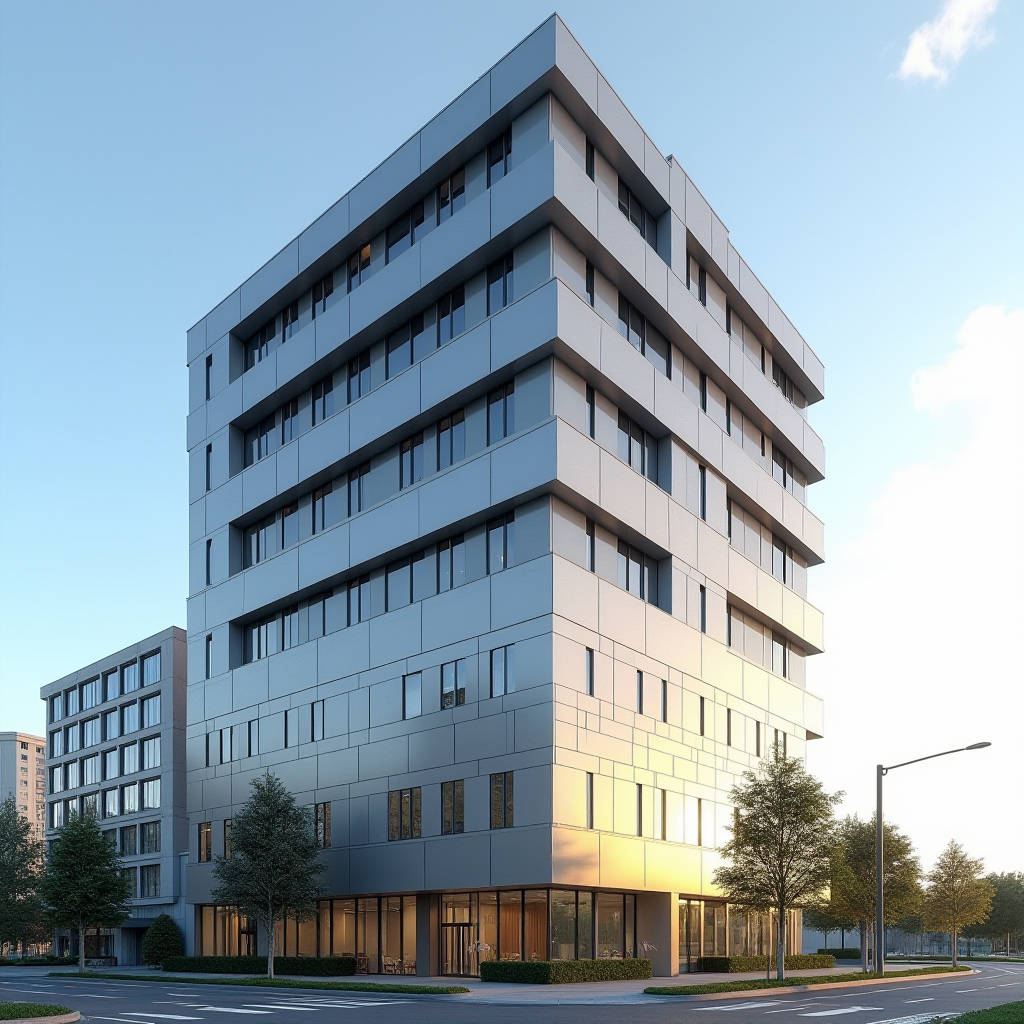
Aluminum Facade Thermal Performance is rarely a single number on a datasheet. It is the sum of decisions made across the cladding profile, the coating system, the insulation cavity, and the structural connections that carry the panel to the building frame. For a solid aluminium cladding panel, the metal itself is a thermal conductor, so the real engineering work happens at the boundaries: the thermal break, the bracket detailing, and the air cavity behind the panel. This article walks through the measurable variables that determine how a solid aluminium facade behaves across heating and cooling seasons, and how specifiers can translate those numbers into a facade that holds its performance for decades rather than for the first inspection cycle.
Why Solid Aluminium Demands a Different Thermal Conversation
Solid aluminium cladding panels are extruded or roll-formed from a single alloy, typically 3003 or 5005 series, at thicknesses of 2.0, 2.5, or 3.0 mm. Unlike composite panels that carry a polyethylene or mineral core, a solid panel has no internal insulation layer. The panel is a continuous metal skin, and its thermal conductivity is essentially that of the alloy itself, roughly 160 to 190 W/m·K depending on temper. That high conductivity is both the strength and the weakness of the material.
On the positive side, a solid panel distributes absorbed solar heat evenly across its surface, which prevents the localised hotspots that can cause differential expansion and oil-canning in thinner skins. On the negative side, without careful detailing, that same conductivity can turn the facade into a heat sink in winter and a heat source in summer. The thermal performance of an aluminium facade is therefore not a property of the panel alone. It is a property of the assembly, and the assembly is where the design decisions live.
Breaking the Thermal Bridge at the Bracket
The most common failure point in a solid aluminium facade is the metal bracket that connects the panel to the structural frame. A continuous aluminium bracket passing through the insulation layer creates a direct thermal bridge, and the heat flow through that bridge can dominate the facade's overall U-value. The standard remedy is a thermally broken bracket, where a low-conductivity polymer or glass-fibre-reinforced nylon insert separates the outer and inner metal sections.
Specifiers should demand bracket systems with a documented thermal break that reduces the linear thermal transmittance, expressed as the psi-value (Ψ) in W/m·K, of the connection. A well-designed thermally broken bracket can cut the heat flow at the connection by 60 to 75 percent compared with a continuous metal bracket. The difference matters most in cold climates, where condensation risk at the bracket location is highest, and in hot climates, where the same bridge drives cooling load.
For a 2.5 mm solid panel on a 150 mm cavity, a continuous aluminium bracket can raise the effective U-value of the wall assembly by 0.15 to 0.25 W/m²·K. Installing a thermally broken bracket brings that penalty back down to roughly 0.03 to 0.06 W/m²·K. Over a 10,000 m² facade, that difference can represent a meaningful share of the annual HVAC load, which is why the bracket is the first place a performance-driven specifier looks.
Coating Systems and Solar Reflectance
The coating on a solid aluminium panel does more than define its colour. It determines how much solar radiation is absorbed and how much is reflected back into the environment. This is captured by the Solar Reflectance Index (SRI), a combined measure of solar reflectance and thermal emittance on a scale of zero to one hundred. A high SRI keeps the panel surface cooler, which reduces the heat that conducts into the building and the heat that radiates into the air cavity.
For solid aluminium cladding, the dominant coating is PVDF (polyvinylidene fluoride), typically applied at a dry film thickness of 25 to 30 microns over a corrosion-resistant primer. The pigment choice drives the reflectance. A standard dark grey PVDF may absorb 70 percent of incident solar energy, while a light metallic or white PVDF finish can reflect 60 to 70 percent. The difference in surface temperature can be 15 to 25 °C on a sunny afternoon, and that surface temperature difference translates directly into conductive heat gain through the cavity.
In hot climates, the selection of a high-SRI PVDF finish is one of the lowest-cost, highest-impact thermal decisions available. The coating costs little more than a standard finish, yet it reduces peak cooling load and extends the life of the insulation behind the panel by keeping the cavity cooler. The table below summarises how coating choice affects the thermal behaviour of a solid aluminium facade.
| Coating Finish | Typical SRI | Surface Temp Rise Above Ambient (sunny day) | Relative Cooling Load Impact |
|---|---|---|---|
| White / light metallic PVDF | 80–100 | 5–10 °C | Low |
| Mid-tone PVDF | 45–60 | 15–20 °C | Moderate |
| Dark grey / black PVDF | 10–25 | 25–35 °C | High |
| Dark PVDF with low-E clear coating | 25–40 | 18–25 °C | Moderate |
Insulation, Cavity Ventilation, and the Air Gap
Behind the solid panel, the arrangement of the insulation and the air cavity determines whether the facade behaves as a vented rainscreen or as a sealed system. A vented rainscreen, where a drained and ventilated cavity sits between the panel and the insulation, is the preferred configuration for solid aluminium cladding in most climates. The ventilated cavity removes moisture vapour and allows the panel to shed heat, while the insulation layer, typically mineral wool or PIR board at 100 to 200 mm, carries the primary thermal resistance.
The cavity depth influences ventilation effectiveness. A cavity of 25 to 40 mm with open joints at the head and sill allows natural convection to move air upward, carrying heat away from the panel surface. Sealing the cavity too tightly turns the air gap into a still layer that conducts heat from the panel into the insulation. The balance between ventilation for moisture control and the desire for a still air layer for insulation is a classic facade trade-off, and the correct answer depends on the local climate and the orientation of the wall.
In a hot climate, a ventilated cavity can reduce the heat flux through the facade by 20 to 30 percent compared with a sealed cavity, because the moving air removes a share of the solar heat before it reaches the insulation. In a cold climate, the same cavity must be detailed to prevent the panel from cooling the insulation layer and creating condensation at the vapour barrier. The specification of the cavity is therefore a climate-specific decision, not a one-size-fits-all detail.
Condensation Risk and the Dew Point
Where a solid aluminium facade meets a cold exterior, the location of the dew point inside the wall assembly becomes a matter of durability. If water vapour condenses on the back of the panel or inside the cavity, it can corrode the metal, degrade the insulation, and support mould growth. The design objective is to keep the dew point out of the metal and the insulation, which is achieved by placing a vapour barrier on the warm side of the insulation and by ensuring the cavity is ventilated to the exterior.
For a solid panel, the risk is higher than for a composite panel because the metal is a better conductor and reaches the exterior temperature more quickly. A specifier should run a dew point analysis for the specific assembly and climate, using the outdoor design temperature and the interior humidity conditions. The result tells you whether the vapour barrier should be a low-permeance membrane or a more permeable layer, and whether additional insulation is needed to keep the interior surface of the panel above the dew point.
Standards and Verification
Thermal performance claims for aluminium facades should be verified against recognised test methods rather than accepted on the strength of a brochure. The relevant references include the ISO 6946 standard for the calculation of thermal resistance and transmittance of building components, and the AAMA 501 test methods for the performance of exterior wall systems. The ASTM C1363 test method covers the steady-state thermal transmission properties of building assemblies, and it is the basis for many U-value certifications.
For the coating, the AAMA 2605 specification sets the performance requirements for high-performance organic coatings on aluminium extrusions and panels, including colour retention and chalk resistance. A coating that meets AAMA 2605 will hold its solar reflectance for a longer service life than a coating that meets only the lower AAMA 2603 level, and that longevity matters because a facade that loses its reflectance over time also loses its thermal benefit. The ISO 6946 calculation method and the AAMA performance standards are the two documents a specifier should keep on the desk when evaluating a solid aluminium facade system.
For the structural and thermal performance of the bracket system, the ASTM C1363 guarded hot box test is the appropriate verification, because it measures the actual heat flow through the assembly rather than a calculated value. The NFRC rating methodology, while developed for fenestration, offers a useful framework for communicating the thermal performance of a facade component in a standardised way.
Practical Specification Guidance
Translating these principles into a procurement specification requires a clear set of measurable requirements. The following checklist covers the essentials for a solid aluminium cladding facade with a defined thermal brief.
- Require a thermally broken bracket with a documented linear thermal transmittance (Ψ-value) below 0.1 W/m·K.
- Specify the PVDF coating to AAMA 2605 with a stated minimum SRI for the selected colour, and require the reflectance to be verified by the coating supplier.
- Define the cavity depth and ventilation strategy explicitly, and confirm the cavity is drained and ventilated to the exterior in accordance with the rainscreen design.
- Run a dew point analysis for the assembly and climate, and specify the vapour barrier position and permeability based on that analysis.
- Require a U-value calculation for the complete wall assembly using ISO 6946, and ask the facade supplier to confirm the calculation inputs.
- Verify the panel thickness and alloy against the specification, and confirm the PVDF film thickness is within the 25 to 30 micron range.
For a project that needs a reliable supply of solid aluminium cladding panels with consistent alloy, thickness, and coating quality, a supplier such as Futeng® can provide panels that meet the dimensional and coating tolerances required for the thermal performance strategy to work. The thermal performance of the assembly depends on the quality of every component, and a panel that arrives with the wrong thickness or an inconsistent coating will undermine the whole design.
The Assembly, Not the Panel, Is the Performance
Aluminum Facade Thermal Performance is best understood as a system property. The solid aluminium panel is a durable, lightweight, and recyclable skin, but its thermal behaviour is decided by the bracket, the coating, the cavity, and the insulation that surround it. A specifier who treats the panel as the only variable will miss the largest opportunities for improvement, while a specifier who manages the assembly as a whole can achieve a facade that performs well in both heating and cooling seasons.
The practical advice is to start with the bracket, because that is where the largest thermal bridge sits, then move to the coating for solar control, and finally tune the cavity and insulation for the specific climate. Verify each decision against a recognised test method, and require the supplier to document the inputs to the calculation. Done this way, a solid aluminium facade delivers the thermal performance that the design intends, and it holds that performance for the service life of the building.