Seismic Resistant Aluminum Facade Engineering for Solid Aluminium Panels in High Drift Zones
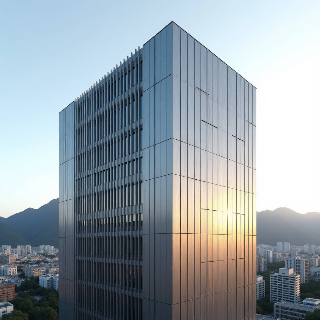
When a building moves under seismic load, the facade is the first line between life and failure. A Seismic Resistant Aluminum Facade is not a single panel or a thicker sheet; it is an engineered assembly where the panel, the substructure, and the anchor system work together to absorb lateral displacement without detaching or cracking. For contractors and procurement managers specifying solid aluminium cladding in high-intensity seismic zones, the distinction between the building structure and the facade system is critical. The structure resists the earthquake, but the facade must survive the building's movement. This article focuses on the engineering decisions that determine whether a solid aluminium panel system performs as a life-safety component or becomes a falling hazard, with concrete data on panel thickness, anchor flexibility, and substructure design.
Why Solid Aluminium Behave Differently Under Earthquake Loads
Aluminium's high strength-to-weight ratio creates a specific seismic profile. A lighter panel generates lower inertial forces during ground acceleration, which is an advantage. At the same time, lighter construction offers less resistance to wind overturning, which means wind loads can often govern the design of aluminium structures. The practical consequence is that a Seismic Resistant Aluminum Facade must be engineered for two simultaneous demands: enough stiffness to resist wind pressure, and enough flexibility to follow the building's inter-story drift without overstressing the panel or its anchors.
Concrete and masonry facades exhibit poor behavior under cyclic seismic loading because they are rigid and brittle. Solid aluminium panels, by contrast, yield plastically before failure, absorbing energy through deformation. This ductility is the reason unitized aluminium curtain wall systems are preferred in high-intensity earthquake-prone areas. The specification priority is high-precision fabrication and high-stability joints, so the system retains sufficient seismic redundancy to resist strong ground motion.
Panel Thickness and the Load Path
The load path in a solid aluminium facade runs from the panel face, through the stiffeners and brackets, into the mullion, and finally to the building structure. Each link in this chain must accommodate movement. Panel thickness is the first variable. For solid aluminium cladding sheets, the industry standard range is 2.0 mm, 2.5 mm, and 3.0 mm. The choice is not purely structural; it affects flatness, deflection under wind, and the weight that the substructure must carry.
In a seismic zone, the panel thickness interacts with the anchor design. A thicker 3.0 mm panel is stiffer and resists local buckling better, but it also adds mass and increases the inertial force transmitted to the anchors during an earthquake. A 2.0 mm panel is lighter but requires more stiffening to control deflection. The correct selection depends on the module size and the local wind regime, not on a blanket rule.
Anchor Flexibility and Energy Absorption
Seismic engineering for metal facades requires that panels, substructures, and anchor systems incorporate flexibility and energy absorption. This is the defining requirement of a Seismic Resistant Aluminum Facade. The anchor system must allow the facade to move with the building during an earthquake while maintaining overall integrity. Rigid connections that lock the panel to the structure will crack or tear the panel when the building drifts.
Two anchor philosophies dominate the market. The first is a fixed anchorage with slotted holes, which allows controlled sliding in one direction. The second is a spring-loaded or elastomeric bearing connection that permits multi-directional movement. For inter-story drift values above 1.5 percent of story height, a purely fixed connection is inadequate. The engineer must specify anchors rated for the expected drift, and the procurement team must verify that the supplied brackets meet that rating rather than assuming all stainless steel anchors are equivalent.
Substructure Design and Inter-Story Drift
The substructure transfers facade loads to the building frame and must be detailed to accommodate the relative movement between floors. In a unitized system, each panel module is installed with a defined gap that closes and opens as the building sways. The mullion splice must allow vertical movement without binding, and the horizontal joints must be sized for the full expected drift plus a safety factor.
Typical engineering practice for seismic zones specifies a design inter-story drift of 1.5 to 2.0 percent of story height for the facade, even when the structural code permits a lower drift for the frame. This conservative approach ensures the facade does not become the limiting element. The joint width is calculated from the drift, the panel thermal movement, and the fabrication tolerance. A common rule is to size the joint so that at maximum drift the panels do not contact each other, which would transmit load and cause spalling or cracking.
Coating and Surface Protection in Seismic Climates
Seismic zones frequently coincide with coastal or high-UV environments, so the coating specification is part of the seismic package. A Seismic Resistant Aluminum Facade must survive both the dynamic load and decades of environmental exposure, because a corroded anchor or a delaminated coating undermines the structural redundancy that the design relies on.
For solid aluminium sheets, the standard protective finish is a PVDF (polyvinylidene fluoride) coating with a dry film thickness of 25 to 30 microns. This coating provides excellent weatherability and color retention. The coating alone does not resist corrosion at cut edges and fastener holes, so the fabricator must apply edge sealant and use stainless steel or aluminium fasteners that are galvanically compatible. The table below summarizes the practical coating parameters for solid aluminium panels in seismic and coastal zones.
| Parameter | Standard Specification | Seismic Zone Requirement | Reason |
|---|---|---|---|
| PVDF dry film thickness | 20-25 microns | 25-30 microns | Higher thickness resists chalking and erosion over 30-year life |
| Panel thickness | 2.0-3.0 mm | 2.5-3.0 mm for large modules | Reduces local buckling and flutter under dynamic load |
| Anchor material | Galvanized steel | Stainless steel 304/316 | Prevents corrosion at the critical load-transfer point |
| Joint width | 10-15 mm | 20-30 mm by drift calculation | Accommodates inter-story drift plus thermal movement |
| Edge protection | None | Sealed cut edges | Prevents corrosion initiation at exposed aluminium |
Fabrication Tolerance and Quality Control
The seismic performance of a solid aluminium facade depends heavily on fabrication precision. A unitized curtain wall system only provides the required redundancy if the panels are manufactured to tight tolerances. Dimensional variation in the panel edges, the bracket positions, or the mullion lengths directly reduces the available joint clearance and can cause premature contact during drift.
For seismic applications, the fabrication tolerance for panel width and height is typically plus or minus 1.0 mm, and the diagonal tolerance is plus or minus 1.5 mm. The bracket hole positions must be controlled to plus or minus 0.5 mm so that the slotted anchor movement is not consumed by fabrication error. Suppliers that cannot hold these tolerances should be excluded from seismic projects, because field adjustment of a rigid facade is costly and rarely achieves the intended performance. Futeng® has supplied solid aluminium panels for seismic projects where this level of dimensional control was a contractual requirement, and the fabrication records were audited against the drift calculations before installation began.
Regulatory and Testing Framework
Specifying a Seismic Resistant Aluminum Facade requires aligning with recognized standards rather than relying on a supplier's marketing claims. The relevant framework includes the seismic provisions of the building code, the aluminium structure design standard, and the facade test methods. Three references are essential for the specifier.
The American Institute of Steel Construction publishes guidance on the seismic design of steel and aluminium structures that informs the connection detailing. The American Architectural Manufacturers Association provides the AAMA 501 test method for dynamic water penetration and the AAMA 501.4 for seismic movement capability of exterior walls. The International Organization for Standardization publishes ISO 8113 for the resistance of glass and panels to cyclic pressure, which is adapted for facade cladding in some regions. The American Society for Testing and Materials publishes ASTM E330 for structural performance of exterior walls, which many projects use as the basis for the static load test.
The critical test for a seismic facade is the cyclic racking test, which simulates the inter-story drift by displacing the top of the facade relative to the bottom. The facade must survive the specified number of cycles at the design drift without glass breakage, panel detachment, or water penetration. This test is not always required by local code, but it is the only reliable way to verify that the anchor system and joint design actually perform as calculated.
Cost and Procurement Considerations
Seismic-rated solid aluminium facades cost more than standard cladding, and the premium is concentrated in the anchors, the joint detailing, and the quality control. A realistic estimate for a seismically detailed unitized aluminium facade is 15 to 25 percent higher than a standard curtain wall, with the anchor and connection hardware accounting for roughly half of that premium. The fabrication tolerance control and the additional testing add the remainder.
For procurement managers, the cost comparison should be made on the installed system, not the panel price alone. A cheaper panel with inadequate anchors will fail the cyclic racking test and require rework, which is far more expensive than specifying the correct hardware from the start. The table below compares the installed cost drivers for a standard versus a seismic-rated solid aluminium facade in a mid-rise project.
| Cost Component | Standard Facade | Seismic-Rated Facade | Premium |
|---|---|---|---|
| Panel supply (2.5 mm, PVDF) | Base | Base + 5% | Higher tolerance and edge sealing |
| Anchor and connection hardware | Base | Base + 40% | Stainless steel, slotted, rated for drift |
| Substructure and mullions | Base | Base + 10% | Reinforced splices and movement joints |
| Testing and certification | Base | Base + 20% | Cyclic racking and water penetration tests |
| Installation labor | Base | Base + 15% | Precision alignment and joint verification |
Practical Guidance for the Specifier
For a project in a high-intensity seismic zone, the specification should start with the inter-story drift value from the structural engineer, not with a panel thickness. From that drift, the joint width, the anchor movement capacity, and the mullion splice detailing are derived. The panel thickness is then selected to control deflection under the governing wind load, and the coating is chosen for the local environment.
The procurement team should request the following from any supplier: fabrication tolerance documentation, the cyclic racking test report for the proposed anchor system, and the material certificates for the solid aluminium sheets and the stainless steel hardware. A supplier that cannot provide these documents should not be considered for a seismic project, regardless of price. The facade is a life-safety system, and the verification evidence is the only protection against a specification that looks correct on paper but fails in the field.
Finally, the installation sequence matters. A correctly designed Seismic Resistant Aluminum Facade is only as good as its installation. The joint widths must be verified on site, the anchors must be torqued to the specified value without over-tightening the slotted connection, and the movement joints must remain free of debris and sealant that would lock the panels together. Field inspection of these details is not optional; it is the last line of defense in converting an engineered design into a building that survives the ground shaking.