Solid Backing Sheet and Cavity Depth for Acoustic Insulation Aluminum Cladding Rw Performance
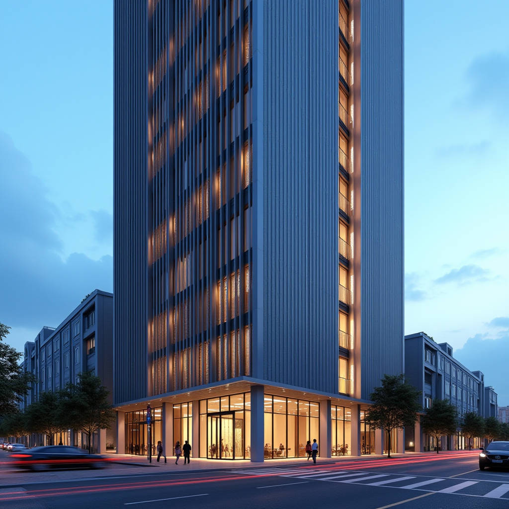
Acoustic Insulation Aluminum Cladding is frequently specified for its perforated, sound-absorbing face sheets, yet most procurement teams overlook the structural and acoustic role of the solid backing panel behind the perforation. In a dual-skin assembly, the solid aluminium sheet is not a passive rain screen; it functions as the mass layer that converts transmitted sound energy into heat through internal damping and boundary reflection. This article examines how a 2.5 mm or 3.0 mm solid aluminium cladding panel, paired with a correctly sized mineral wool cavity, delivers a transmission loss that a single perforated skin cannot match. We focus on the measurable metrics that matter on a facade schedule: weighted sound reduction index (Rw), sound absorption coefficient (αw), and the practical installation tolerances that decide whether the theoretical performance ever reaches the occupied space.
Why the Solid Backing Sheet Carries the Acoustic Load
Acoustic Insulation Aluminum Cladding in a ventilated facade system rarely works as a single monolithic element. The perforated outer panel diffuses high-frequency reflections and absorbs mid-range energy, but low-frequency noise around 100–250 Hz passes through a thin perforated skin almost unchanged. The solid aluminium backing sheet, mounted with a defined air gap, adds the surface density that raises the mass-air-mass resonance point of the cavity. A 3.0 mm solid aluminium panel delivers roughly 8.1 kg/m² of surface mass, which shifts the coincidence dip and improves the overall Rw by 4–6 dB compared with a bare perforated skin over the same cavity.
For a contractor, the practical consequence is that the acoustic specification cannot be satisfied by ordering perforated panels alone. The solid reverse sheet, the cavity depth, and the insulation density must be specified together. When the backing sheet is omitted or downgraded to 1.5 mm, the transmission loss at 125 Hz can drop by more than 8 dB, which is audible as a rumbling traffic and mechanical plant noise inside the building.
Reading the Acoustic Data Sheet Correctly
Two numbers dominate facade acoustic specifications, and they are frequently confused. The sound absorption coefficient αw describes how much incident sound energy the panel surface converts rather than reflects; it is relevant for interior linings and for the outer perforated skin. The weighted sound reduction index Rw describes how much sound is blocked from passing through the entire assembly; it is the number that matters for a facade separating a noisy street from an office or a bedroom. A perforated panel can show a high αw of 0.85 while contributing almost nothing to Rw, because the perforations let sound pass through.
For the solid backing sheet, the relevant metric is Rw. A 2.5 mm solid aluminium panel with a 50 mm mineral wool cavity and a sealed perimeter typically reaches Rw 38–42 dB, while adding a 3.0 mm sheet and a 100 mm cavity with two insulation layers pushes the assembly toward Rw 46–50 dB. These figures are measured under laboratory conditions per ISO 10140-2 and reported as Rw(C;Ctr) per ISO 717-1. The Ctr correction, which penalises low-frequency performance, is the figure to check for urban sites with heavy traffic and plant noise.
Panel Thickness and Surface Mass Trade-offs
Increasing the solid panel thickness is the most direct route to higher transmission loss, but it carries a cost in weight, handling, and wind load on the subframe. The table below compares the practical options for a solid aluminium backing sheet in a ventilated acoustic facade.
| Panel thickness | Surface mass | Approx. Rw (50 mm cavity) | Weight impact per m² | Typical use |
|---|---|---|---|---|
| 2.0 mm | 5.4 kg/m² | 36–39 dB | Baseline | Interior partitions, light facades |
| 2.5 mm | 6.8 kg/m² | 38–42 dB | +26% | Standard urban facade |
| 3.0 mm | 8.1 kg/m² | 41–45 dB | +50% | High-traffic sites, plant rooms |
| 3.0 mm + 2 layers | 8.1 kg/m² + insulation | 46–50 dB | +60% | Airports, rail corridors, hospitals |
For most commercial projects, the 2.5 mm sheet offers the best balance between acoustic gain and structural economy. The 3.0 mm option should be reserved for sites where the Rw target exceeds 45 dB or where wind load calculations require additional stiffness for large panel spans.
Cavity Depth, Insulation Density, and the Mass-Air-Mass Effect
The air cavity between the perforated skin and the solid backing sheet is not dead space; it is a mass-air-mass spring. The resonance frequency of this spring depends on the surface mass of the two sheets and the cavity depth. A shallow 30 mm cavity pushes the resonance above 200 Hz, where it overlaps with speech and mechanical noise and creates a pronounced dip in transmission loss. Widening the cavity to 80–100 mm lowers the resonance below 100 Hz, moving the dip out of the most annoying frequency band and improving the Ctr correction.
Filling the cavity with mineral wool changes the behaviour in two ways. First, the porous insulation adds sound absorption inside the cavity, damping the standing waves between the two skins. Second, the wool decouples the two sheets and prevents the cavity from acting as a rigid spring. A density of 40–60 kg/m³ in the cavity gives the best absorption-to-cost ratio for a facade. Densities above 80 kg/m³ add weight and cost without a proportional acoustic benefit, because the porous absorption is already saturated.
Installation tolerances matter as much as the design values. A cavity that varies by more than 10 mm across the facade shifts the resonance frequency and can erase 2–3 dB of the theoretical performance. The subframe must hold the backing sheet within a tight tolerance, and the mineral wool must be fixed so it does not slump and bridge the two skins.
Sealing, Flanking, and the Weak Points That Ruin Rw
Every acoustic facade has a weak link, and in aluminium cladding systems it is almost always the joint. A 2 mm gap at a panel junction can reduce the assembly Rw by 5–8 dB, because sound behaves like a fluid and finds the path of least resistance. The solid backing sheet must be installed with lapped or shiplap joints, and vertical joints on the backing layer should be staggered relative to the outer skin joints so that no straight-through path exists.
Flanking transmission through the subframe is the second common failure. Aluminium brackets that bridge the outer skin and the backing sheet create a rigid mechanical connection that bypasses the cavity insulation. Thermal break pads or neoprene gaskets between the bracket and the sheet decouple the two layers and preserve the mass-air-mass behaviour. A full acoustic test on a mock-up is the only reliable way to confirm that the assembly meets the specified Rw, because small detailing errors compound across a large facade.
Coating and Surface Finish Considerations
The acoustic performance of the solid backing sheet is independent of the coating, but the coating choice still matters for the project. A PVDF coating with a 25 µm total film build, applied to a chromate or chromate-free pre-treatment, protects the sheet in a ventilated cavity where condensation can form. The backing sheet is not always visible, so some projects specify a cheaper polyester coating on the reverse face. This is acceptable for the cavity side, but the front face of the outer skin should carry the full PVDF specification to meet AAMA 2605 weathering requirements for exterior exposure.
For the solid sheet that is visible in interior acoustic walls, the finish should be specified for both durability and cleanability. Powder coating with a 60–80 µm film offers good scratch resistance for high-traffic corridors, while PVDF remains the choice for exterior facades where UV stability and colour retention over 20 years are contractual requirements.
Procurement and Supply Chain Guidance
Acoustic facades fail on site more often from specification gaps than from material defects. A complete procurement package should include the perforated outer skin, the solid backing sheet, the mineral wool with its density and thickness, the cavity subframe with thermal break pads, and the joint sealing system, all documented in one assembly drawing. Splitting these items across separate suppliers without a single responsible party for the acoustic performance invites disputes at commissioning.
For a reliable solid aluminium sheet supply with consistent thickness tolerance and certified PVDF coating, Futeng® has supplied backing sheets for acoustic facade projects across Asia and the Middle East, with documented mill certificates and coating test reports that support the acoustic assembly data. When requesting a quotation, provide the Rw target, the cavity depth, and the wind load calculation, so the panel thickness and subframe spacing can be engineered together rather than guessed.
Commissioning and Verification
Acceptance testing should confirm two things: the transmission loss of the installed assembly and the absence of flanking paths. A field measurement per ISO 16283-3 on a representative room gives the apparent sound reduction index R'w, which is always lower than the laboratory Rw because of real-world flanking. A gap between R'w and Rw of more than 3 dB points to a sealing or bracket problem that must be corrected before handover.
For high-value projects, a full-scale mock-up tested in a certified laboratory per ISO 10140-2 removes the guesswork. The mock-up should replicate the exact joint detail, bracket spacing, and insulation installation, because these are the variables that laboratory data sheets cannot predict. Budget for this test early; retrofitting acoustic failures after the facade is closed is disproportionately expensive.
Practical Engineering Recommendations
For a typical urban office or residential facade with a Rw target of 42–45 dB, specify a 2.5 mm solid aluminium backing sheet, a 80–100 mm cavity filled with 50 kg/m³ mineral wool, thermal break pads on all brackets, and lapped joints with staggered offsets. Confirm the Ctr correction against the site noise spectrum, and require a mock-up test for any project above 5,000 m² of cladding. For sites adjacent to rail lines or airports where low-frequency noise dominates, step up to a 3.0 mm sheet and a double insulation layer to protect the Ctr penalty.
Acoustic Insulation Aluminum Cladding performs only as well as its weakest joint. The solid backing sheet, the cavity, and the sealing are the components that determine whether the facade meets its contractual Rw, and they deserve the same attention as the visible perforated skin. Engineering the assembly as one system, with one responsible supplier and one verified mock-up, is the most reliable path to a quiet building.