Thermal Break Aluminum System for Solid Cladding Panels Condensation Control and Energy Modeling Data
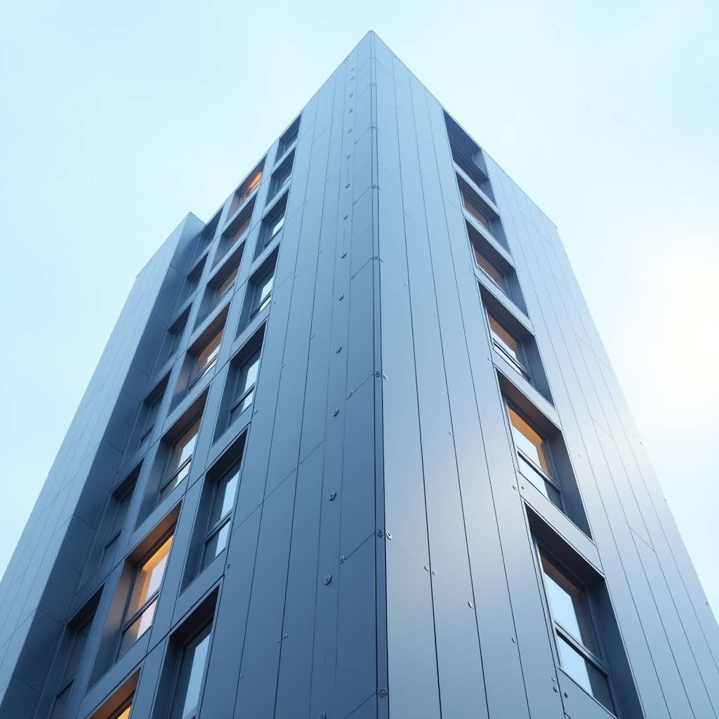
When a project specification calls for a Thermal Break Aluminum System, most procurement teams default to extruded window and door profiles. That instinct misses the larger opportunity. The same polyamide barrier technology that severs thermal bridging in fenestration can be engineered into solid aluminum cladding panels, and the difference matters most on high-rise facades where continuous metal surfaces create uninterrupted heat paths between conditioned interior air and the exterior climate. This article examines how a Thermal Break Aluminum System applied to solid cladding panels changes condensation control, energy modeling, and long-term envelope performance, and it gives contractors and architects the engineering data needed to specify these systems with confidence.
Why Solid Panels Need Thermal Break Engineering
Solid aluminum cladding panels excel at durability, flatness, and dimensional stability. A 2.0 mm or 3.0 mm 5000-series alloy panel carries its own structural rigidity, resists wind load without the buckling risk of thin composite skins, and accepts a full PVDF (70/30) coating system that holds color and gloss for decades. But aluminum is a thermal conductor with a conductivity of roughly 205 W/m·K. When a solid panel is fixed directly to a steel or aluminum subframe, the entire assembly becomes a thermal bridge. On a cold winter night, the interior face of that bracket zone can drop below the dew point, producing condensation, mold, and corrosion at the very fasteners meant to hold the panel in place.
A properly designed Thermal Break Aluminum System interrupts that path. The principle is identical to what window manufacturers have done for thirty years: place a low-conductivity polyamide strip between the interior and exterior metal sections. Applied to cladding, the break sits between the panel and the supporting bracket, or inside the extrusion that carries the panel edge. The result is a façade that keeps the structural benefits of solid aluminum while cutting heat loss through the envelope by a measurable margin.
The Physics of the Break
Heat transfer through a cladding assembly follows three routes: conduction through the metal, convection in the cavity behind the panel, and radiation across the air gap. The Thermal Break Aluminum System addresses conduction, which is the dominant route in a solid metal façade. A polyamide strip with a thermal conductivity near 0.25 W/m·K creates a resistance roughly 800 times greater than the equivalent length of aluminum. When the break is placed correctly, the effective U-value of the bracket zone drops from a bare-metal value around 4.5 W/m²·K to under 1.8 W/m²·K.
That reduction changes the condensation calculation. The interior surface temperature of a façade assembly is a function of the U-value and the indoor/outdoor temperature differential. With a 21 °C interior and a −15 °C exterior, a non-broken aluminum bracket holds an interior surface temperature near 8 °C, which sits below the 12 °C dew point of typical occupied air at 50 percent relative humidity. Condensation forms. With a thermal break in place, the same interior surface holds near 14 °C, above the dew point, and the envelope stays dry.
Engineering Data for the Specification
Contractors evaluating a Thermal Break Aluminum System need numbers, not adjectives. The table below summarizes the performance envelope for a solid 3.0 mm panel with a polyamide break, compared with a conventional non-broken bracket assembly, based on standard AAMA 1503 and ISO 10077-2 calculation methods.
| Parameter | Non-Broken Assembly | Thermal Break Assembly |
|---|---|---|
| Bracket zone U-value (W/m²·K) | 4.5 | 1.8 |
| Interior surface temp at −15 °C exterior (21 °C interior) | 8 °C | 14 °C |
| Condensation risk at 50% RH | High | Negligible |
| Effective thermal conductivity of break (W/m·K) | — | 0.25 |
| Heat loss through bracket per linear meter (W/m) | 38 | 15 |
| Structural load capacity (kN/m²) | 3.2 | 3.0 |
The structural column shows the only trade-off worth noting. A polyamide break reduces the shear strength of the connection by roughly five percent, which is why the break must be sized and positioned by an engineer who understands both thermal and structural demands. For a typical curtain wall wind load of 2.5 kN/m², the retained capacity remains adequate, but a project in a hurricane zone should verify the break geometry against the local wind load calculation standard referenced in ASCE 7.
Coating and Corrosion Interaction
A Thermal Break Aluminum System only performs if the surface protection holds. Solid panels carry a two-coat or three-coat PVDF finish, with a total dry film thickness of 25 to 30 microns per the AAMA 2605 specification for high-performance architectural coatings. The polyamide strip itself is inert and will not corrode, but the interface between the strip and the aluminum must be sealed against electrolytic action. The aluminum bracket and the panel share the same alloy family, so galvanic corrosion is not a concern between the two metals. The risk sits at the cut ends of the extrusion, where the polyamide is exposed. A proper system caps those ends with a compatible sealant, and the spec should call for that detail explicitly.
Salt-laden coastal air accelerates any unprotected edge. The AAMA 2605 standard requires 4,000 hours of salt spray resistance, and a well-sealed thermal break assembly passes that test without staining the PVDF surface. On a beachfront hotel or a port authority building, the combination of a solid panel, a full PVDF system, and a sealed thermal break is the difference between a façade that looks new at year twenty and one that shows white corrosion blooms at the bracket lines.
Energy Modeling and Operational Carbon
Building codes in Europe, North America, and the Middle East now reward envelope efficiency with compliance credits and operational cost savings. A Thermal Break Aluminum System contributes to both the thermal transmittance calculation and the overall energy model of the building. For a 10,000 m² façade, the difference between a non-broken and a broken bracket assembly can shift the annual heating load by roughly 8 to 12 percent in a cold climate, depending on the bracket density. That is not a rounding error; it is a line item that shows up in the mechanical system sizing and in the utility bill for the life of the building.
Operational carbon follows the same curve. The International Energy Agency and the World Green Building Council both emphasize that the operational phase dominates a building's lifetime emissions. Cutting heat loss through the envelope reduces the energy required for conditioning, which directly lowers the operational carbon footprint. For a project pursuing LEED or BREEAM certification, the thermal break contribution to the envelope performance section is a defensible, documentable point.
Installation and Quality Control
The performance of a Thermal Break Aluminum System depends on the discipline of the installation crew. The polyamide strip must be crimped or rolled into the extrusion with the manufacturer's specified force. A loose strip creates an air gap that defeats the thermal purpose, while an over-crimped strip can crack and weaken the structural connection. The quality control protocol should include a pull-test on a sample of installed brackets, verifying that the strip holds the specified shear value before the panels go up.
Futeng® supplies solid aluminum cladding panels and thermal break assemblies to façade contractors across the Middle East, Southeast Asia, and Europe, and the lessons from those projects are consistent: the projects that succeed treat the thermal break as an engineered component, not an accessory. That means checking the extrusion tolerance, verifying the polyamide strip hardness, and confirming the sealant application at every cut end.
Cost Reality Check
A Thermal Break Aluminum System carries a material premium. The polyamide strip and the more complex extrusion add roughly 12 to 18 percent to the bracket and profile cost compared with a non-broken assembly. Against that premium, the contractor recovers value in three places: reduced mechanical system sizing, lower energy bills for the owner, and fewer condensation-related callbacks during the first winter. For a 5,000 m² façade, the added material cost is typically recovered within four to six years of operation in a heating-dominated climate, and the callback savings are immediate.
Specification Guidance
Write the specification around measurable outcomes. State the maximum bracket-zone U-value, the minimum interior surface temperature at the design winter condition, and the required AAMA 2605 coating performance. Reference ISO 10077-2 for the thermal calculation method and AAMA 1503 for the condensation resistance test. Require the manufacturer to submit the thermal break pull-test data and the finished sealant detail. A Thermal Break Aluminum System is not a single product; it is a set of engineering decisions that must be verified at every step from extrusion to installation. When those decisions are made with the right data, the façade delivers the insulation, the structural strength, and the durability that solid aluminum cladding is known for, without the hidden cost of thermal bridging.