Thermal Insulation Aluminum Facade Performance Driven by Bracket Breaks and Air Tightness
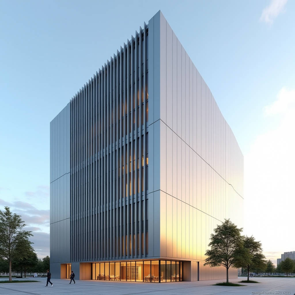
Thermal Insulation Aluminum Facade performance is rarely decided by the panel itself. Solid aluminium cladding sheets act as the weatherproof skin, but the real thermal story lives in the jointing, the bracket system, and the insulation core behind the metal. For specifiers and contractors working on curtain walling and rainscreen projects, the recurring failure is not material choice but thermal bridging at every fastener and support that penetrates the insulation layer. Aluminium conducts heat roughly 1,500 times faster than still air, so a single unbroken aluminium bracket can undo the work of 100 mm of mineral wool. This article walks through the engineering parameters that separate a genuinely insulated facade from one that merely looks insulated, with practical numbers for U-value budgeting, bracket design, and installation sequencing.
The Physics Constraint That Drives Every Decision
Every facade assembly is a chain of thermal resistances. The solid aluminium panel contributes almost nothing to insulation, roughly 0.003 m²K/W for a 3.0 mm sheet. The insulation layer, the air cavity, and the bracket system carry the load. The governing equation is simple: the total thermal transmittance of the wall assembly is the sum of all series resistances, but parallel paths through metal create shortcuts that bypass the insulation entirely. This is why a Thermal Insulation Aluminum Facade must be evaluated as a system, not as a sum of components.
For a typical rainscreen assembly targeting a whole-wall U-value around 0.30 W/(m²K), the bracket system becomes the critical variable. A continuous aluminium angle bracket spanning the full depth of the insulation layer can create a thermal bridge that raises the effective U-value by 15 to 25 percent. The fix is thermal break pads, typically glass-fibre reinforced polyamide or high-density polyethylene, inserted between the aluminium bracket and the substrate. These pads reduce the point transmittance coefficient from roughly 0.10 W/K per bracket to below 0.03 W/K.
Quantifying the Bracket Penalty
Project teams should calculate the point thermal transmittance (chi-value) for every fixing. A standard 100 mm deep aluminium bracket with no break, spaced at 600 mm centres, contributes approximately 0.08 to 0.12 W/K per fixing. Multiply that by the number of fixings per square metre, typically 4 to 6, and the penalty becomes visible. With a thermal break pad in place, the same bracket drops to 0.02 to 0.04 W/K. Over a 10,000 m² facade, that difference is the equivalent of adding 20 to 30 mm of insulation across the entire wall.
| Bracket Configuration | Point Transmittance (W/K) | Effect on Whole-Wall U-value | Relative Cost Factor |
|---|---|---|---|
| Continuous aluminium angle, no break | 0.08 – 0.12 | +0.05 to +0.08 W/(m²K) | 1.0 |
| Aluminium bracket with polyamide pad | 0.02 – 0.04 | +0.01 to +0.02 W/(m²K) | 1.15 |
| Stainless steel bracket with pad | 0.01 – 0.02 | +0.005 to +0.01 W/(m²K) | 1.8 |
| Full thermal break cassette system | < 0.01 | Negligible | 2.2 |
The table above is the working sheet for any facade contractor. The 15 percent cost premium for a polyamide pad is the cheapest insulation money a project will ever spend, because it protects the entire insulation layer from being short-circuited.
Panel Specification and the PVDF Coating Factor
Solid aluminium cladding panels for insulated facades are typically 2.0, 2.5, or 3.0 mm thick, supplied in 5000 or 6000 series alloy. The 3.0 mm grade is common for high-rise curtain walling where flatness tolerance and wind load resistance matter. The coating is a two-coat or three-coat PVDF system, with a dry film thickness of 25 to 30 microns per coat, applied over a chromate or chrome-free conversion layer. While the coating is primarily a durability and colour performance issue, it also affects solar reflectance and therefore the surface temperature that the insulation must manage.
A light-coloured PVDF finish with high solar reflectance keeps the panel surface temperature 15 to 25 °C lower than a dark finish under the same solar load. That lower surface temperature reduces the heat flux into the cavity and lowers the peak temperature the insulation must withstand. For projects chasing passive house or near-passive performance, specifying a high-reflectance finish is a zero-cost insulation upgrade. The relevant performance benchmark is AAMA 2605, the specification for high-performance organic coatings on aluminium, which governs colour retention, chalk resistance, and adhesion over a 10-year accelerated weathering cycle.
Insulation Core Selection Behind the Panel
The material behind the solid aluminium sheet is where most of the thermal work happens. Mineral wool, rigid polyisocyanurate (PIR) board, and extruded polystyrene (XPS) are the common choices, each with trade-offs in fire performance, moisture behaviour, and thermal conductivity. Mineral wool has a lambda value of 0.034 to 0.040 W/(m·K) and is non-combustible, which makes it the default for high-rise and fire-sensitive projects. PIR delivers a better lambda of 0.022 to 0.026 W/(m·K) for the same thickness, but it is combustible and requires a fire barrier strategy in many jurisdictions.
For a 150 mm insulation cavity, mineral wool delivers a U-value contribution of roughly 0.23 W/(m²K), while PIR at the same thickness achieves about 0.16 W/(m²K). The choice is a fire code decision first and a thermal decision second. In most European and North American high-rise applications, the non-combustible route wins. The insulation must also be installed in a way that prevents air movement through the cavity, because convection currents can carry heat around the insulation and degrade its effective performance by 10 to 15 percent.
Air Tightness as an Insulation Strategy
Thermal insulation in a facade is only as good as the air barrier behind it. A continuous air and vapour barrier on the warm side of the insulation prevents moisture-laden interior air from reaching the insulation and condensing. The airtightness requirement for passive house certification is 0.6 air changes per hour at 50 Pa, and the facade jointing system is a major contributor to meeting that number. Every panel joint, every bracket penetration, and every window interface must be sealed and tested.
The practical method is pressure testing a mock-up panel before full production. A 1:1 scale mock-up of the facade, including a window corner and a bracket penetration, is tested to the airtightness target. This identifies weak points in the detailing before thousands of square metres are installed. The test protocol follows the framework of ISO 9972, the standard for measurement of air permeability in buildings. Fixing the leaks found in a mock-up costs a fraction of what it costs to remediate them on a completed facade.
Installation Sequencing That Protects the Insulation
The sequence of installation is as important as the materials. Insulation must be installed and protected before the cladding panels go on, because a rain event during construction can saturate mineral wool and destroy its thermal performance. Mineral wool absorbs water and loses up to 40 percent of its insulating value when wet. The contractor should schedule the insulation installation and the vapour barrier in the same work sequence as the panel fixing, with the panels closing off each bay as soon as the insulation is in place.
For a typical project, the facade team should plan for a bay-by-bay closure rather than installing all insulation across the building first. This reduces weather exposure risk and allows the airtightness to be tested incrementally. Futeng® supplies solid aluminium cladding panels with tolerances that support this tight-sequencing approach, holding flatness within 1.5 mm per metre and panel squareness within 1 mm, which keeps joint gaps consistent and sealant application predictable.
Climate-Specific Design Parameters
The optimum insulation thickness and bracket design depend on the climate zone. In a cold climate, the priority is minimising winter heat loss, and the facade should target a whole-wall U-value below 0.25 W/(m²K). In a hot climate, the priority shifts to solar control, and the reflective finish and the ventilation of the cavity become the dominant factors. A ventilated rainscreen cavity of 40 to 60 mm allows moisture to escape and reduces summer heat gain through natural convection, but it must be detailed to prevent the cavity from acting as a chimney that draws heat in.
The dew point calculation is a mandatory step. The position of the dew point within the facade assembly determines whether condensation forms on the insulation, the vapour barrier, or the panel. If the dew point falls on the insulation, moisture accumulates and performance degrades. Moving the vapour barrier to the warm side of the insulation shifts the dew point out of the insulation layer. This calculation follows the methodology in ISO 6946, the standard for building components and building elements thermal resistance and transmittance.
Whole-Wall U-Value Budgeting
Project teams should budget the whole-wall U-value as a line item, not assume that the insulation lambda alone delivers the target. The whole-wall value includes the panel, the cavity, the insulation, the brackets, the substrate, and the interior finish. A realistic breakdown for a 150 mm mineral wool rainscreen with broken brackets is roughly 0.30 W/(m²K) whole-wall, versus 0.26 W/(m²K) for the insulation layer alone. The 15 percent gap is the bracket and jointing penalty, and it is the line item that separates a well-detailed facade from an average one.
For projects pursuing certification, the facade documentation should include the chi-value calculations for every bracket type, the pressure test report, and the dew point analysis. These three documents are what a certification auditor reviews. Supplying them proactively shortens the approval cycle and reduces the risk of design changes late in the project.
Practical Specification Checklist for Contractors
- Specify a thermal break pad for every bracket that penetrates the insulation layer, and document the chi-value in the shop drawings.
- Select a 2.5 or 3.0 mm solid aluminium panel with a high-reflectance three-coat PVDF finish for hot climates.
- Use non-combustible mineral wool for high-rise and fire-sensitive projects, and confirm the fire classification with the local authority.
- Install the vapour barrier on the warm side of the insulation and verify the dew point position with an ISO 6946 calculation.
- Pressure test a mock-up to ISO 9972 before production, and close each facade bay before the next is insulated.
- Budget the whole-wall U-value, including the bracket and jointing penalty, not just the insulation layer value.
The engineering conclusion is consistent across climates and building types: a Thermal Insulation Aluminum Facade performs only as well as its weakest thermal path. The panel is the visible product, but the bracket break, the air barrier, and the insulation sequencing decide the real U-value. Specifying broken brackets, a continuous air barrier, and a bay-by-bay installation sequence delivers measurable energy performance at a modest cost premium. Contractors who treat thermal bridging as a design parameter to be solved, rather than an unavoidable flaw, consistently produce facades that meet their energy targets on the first attempt.