Wind Load Resistant Aluminum Facade Engineering for Solid Aluminium Panels on High Rise Envelopes
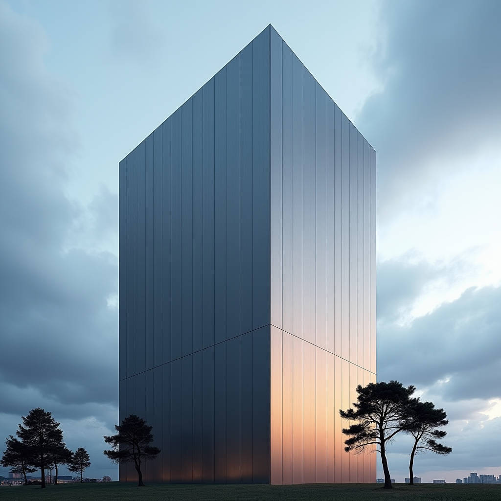
A Wind Load Resistant Aluminum Facade is not a single product but a coordinated structural system in which the solid aluminium panel, its fixing strategy, the subframe geometry, and the sealant regime must all be engineered against site-specific pressure coefficients. For a 2.0 mm to 3.0 mm solid aluminium sheet, the governing question is rarely whether the metal itself can endure the load; it is whether the connection details and the supporting framework can transfer that load into the primary structure without fatigue, excessive deformation, or air and water infiltration. This article walks through the calculation inputs, the test protocols, and the installation tolerances that separate a facade that survives a storm from one that merely looks like it could.
What Actually Drives Wind Load on a Solid Aluminium Panel
Wind pressure on a facade is a function of local wind speed, building height, exposure category, and the pressure coefficients that describe how the building geometry redistributes the flow. For a high-rise tower, the peak negative pressures on corners and parapets can reach two to three times the mean pressure on the central field. That distinction matters because a solid aluminium cladding panel is a flat, rigid element; it does not shed load through curvature the way a profiled sheet might. The panel must be designed for the worst local pressure coefficient, not the building average.
Site-specific wind data is the starting point. The basic wind speed comes from national codes, but the effective design pressure must be adjusted for terrain roughness, topography, and the gust factor. A facade engineer then converts that pressure into a line load on the panel supports and a point load on each fixing. For a 3.0 mm solid aluminium sheet, deflection under peak suction is typically limited to span/60 or L/90 depending on the specification, and the residual deformation after load removal must return to near zero so the panel does not oil-can or permanently crease.
Panel Thickness and the Stiffness Question
Solid aluminium cladding panels are available in 2.0 mm, 2.5 mm, and 3.0 mm thicknesses, and the choice is a direct trade-off between stiffness and cost. A 3.0 mm panel is roughly 1.7 times as stiff in bending as a 2.5 mm panel of the same span, which allows longer unsupported spans and fewer stiffeners. But the weight penalty is real: aluminium at roughly 2.71 g/cm³ means a 3.0 mm panel weighs about 8.1 kg/m² before any coating or backing, versus 6.8 kg/m² for 2.5 mm and 5.4 kg/m² for 2.0 mm.
For most high-rise applications, 2.5 mm is the practical default for the field, with 3.0 mm reserved for corner zones, parapets, and areas where the local pressure coefficient spikes. The 2.0 mm panel is workable on low-rise or sheltered elevations but demands a tighter subframe grid, which can erase the material savings through added framing and labour. The real engineering decision is not the panel thickness in isolation; it is the combination of thickness, stiffener spacing, and the span of the subframe.
Fixing Strategy and Load Path
The way a solid aluminium panel transfers wind load into the structure determines almost everything about its performance. Two fixing families dominate: edge-fixed systems where the panel is captured in a frame or cleat, and back-fixed systems using threaded studs or concealed brackets welded to the back of the panel. Each has a distinct load path and a distinct failure mode.
Back-fixed systems concentrate the load at discrete points, which is efficient for large spans but demands careful attention to the stud weld quality and the bracket stiffness. Edge-fixed systems distribute the load more evenly along the panel perimeter but require a more substantial subframe and are more sensitive to thermal expansion restraint. For a Wind Load Resistant Aluminum Facade on a tall building, the specification should state the allowable movement at each fixing, the bolt torque, and the corrosion protection between the aluminium and any dissimilar metal in the bracket. Steel brackets behind aluminium panels need an isolating washer or a coating to prevent galvanic corrosion, which otherwise silently eats away at the load transfer path.
Testing Protocols That Prove the System
No facade should be accepted on calculation alone. The industry standard practice is to test a full-scale mock-up of the wall assembly under both static and dynamic pressure. The static test applies a uniform air pressure across the specimen and holds it for a defined duration, checking for structural failure, excessive deflection, and residual deformation. The dynamic test cycles the pressure to simulate gust loading and checks for fatigue and loosening of fixings.
Air and water infiltration are tested separately, because a facade that holds its structural load can still leak badly under wind-driven rain. The test sequence typically ramps pressure in steps, and the pass criteria are defined by the project specification, often referencing the AAMA 501 series or the European EN 12179 and EN 12153 standards. A useful benchmark is that a high-rise facade should hold its structural rating at a pressure at least 1.5 times the design wind pressure, with no permanent deformation and no loss of seal integrity.
| Test Parameter | Typical Specification | Reference Standard | Pass Criterion |
|---|---|---|---|
| Static structural pressure | 1.5× design wind pressure | AAMA 501.1 / EN 12179 | No structural failure, no permanent deformation |
| Dynamic gust cycling | 10,000 cycles at 0.5–1.0× design pressure | EN 12153 | No loosening of fixings, no fatigue cracks |
| Air infiltration | Tested at 300 Pa and 600 Pa | ASTM E283 / EN 12153 | Below 0.3 m³/h/m² at 300 Pa |
| Water penetration | Ramped to design pressure | ASTM E331 / EN 12154 | No water reaching interior face |
| Deflection limit | L/60 to L/90 under peak load | Project specification | No residual deformation after unload |
Subframe Layout and Span Engineering
The subframe is where wind load engineering actually happens. For a solid aluminium panel, the subframe typically runs as vertical mullions with horizontal rails, and the spacing of those rails sets the unsupported span of the panel. Halving the span reduces the panel bending stress by a factor of four, which is why a 2.0 mm panel on a tight grid can outperform a 3.0 mm panel on a wide grid. The trade-off is framing cost and thermal bridging, so the engineer balances material weight against the number of connections.
Thermal movement is a hidden variable in wind load design. A solid aluminium panel expands by roughly 0.024 mm per metre per degree Celsius. On a 3-metre panel, a 60°C temperature swing produces about 4.3 mm of movement, which must be accommodated at the joints or the panel will buckle and the fixings will be overstressed. The joint design therefore has to absorb both the wind load deflection and the thermal expansion without transferring excessive force into the brackets. This is why rigidly welded assemblies fail in service even when they pass a static test at ambient temperature.
Coating and Corrosion in a Wind-Exposed Envelope
The wind load story is inseparable from the coating story, because a corroded panel loses its edge bite and its fixing integrity. Solid aluminium panels are typically finished with a two-coat or three-coat PVDF system, with a dry film thickness of 25 to 35 microns for the two-coat system and 35 to 45 microns for the three-coat system. The PVDF resin delivers the colour retention and chalk resistance that a high-rise facade needs over a 20-year-plus service life, and it protects the anodised or bare aluminium substrate from the chloride attack that coastal wind exposure brings.
For coastal projects, the specification should call out the salt-spray performance of the coating and the corrosion resistance of the fixing hardware. Stainless steel fixings are the default in marine zones, and the aluminium-to-steel interface must be isolated. The interaction between wind load and corrosion is cumulative: a corroded bracket loses section, the load path stiffens unevenly, and the panel starts to take on a different stress distribution than the calculation assumed. Regular inspection of the concealed fixings is part of the long-term wind resistance of the system.
Installation Tolerances That Make or Break the Design
A facade that is perfectly engineered on paper fails on site when the subframe is out of tolerance. The panel is machined to tight dimensions, but if the supporting rails are not plumb, level, and square, the fixing points do not align and the panel is forced into a pre-stressed condition before any wind arrives. The installation specification should define the allowable deviation of the subframe, the gap tolerance between panels, and the torque settings for every fixing.
For a Wind Load Resistant Aluminum Facade, the practical rule is that the subframe flatness deviation should not exceed 2 mm over a 3-metre length, and the panel-to-panel gap should be held to the design value plus or minus 1 mm. Setting the correct gap is essential because it is the space that accommodates thermal movement and the sealant that keeps water out. If the gap closes up, the sealant is compressed beyond its design range and the water barrier fails under wind-driven rain.
Choosing a Supplier Who Can Back the Numbers
When the calculation and the test data are on the table, the remaining risk is manufacturing consistency. A solid aluminium cladding panel is only as reliable as the flatness, the coating adhesion, and the dimensional control that come out of the factory. A supplier who can deliver panels to tight tolerances, with documented coating thickness and a consistent alloy temper, removes a large share of the on-site uncertainty. For projects where the wind load case is severe and the panel sizes are non-standard, working with a manufacturer who can produce to the exact thickness and stiffener layout, rather than forcing a stock panel into the design, is a practical advantage. Futeng® has built its reputation on exactly this kind of engineering-led supply for solid aluminium panels, and it is a reasonable reference point when you are qualifying sources for a high-wind project.
Practical Guidance for the Specification
For a project in a high-wind zone, the sequence of decisions is straightforward. Start with the site-specific wind study and extract the peak local pressure coefficients for the corners and parapets. Select the panel thickness and subframe grid together, because they are a single stiffness system. Specify a full-scale mock-up test to the relevant AAMA or EN standard and make the test a contractual gate, not a formality. Then control the installation tolerances and the thermal joint gaps on site, because those are the variables that the calculation cannot see.
The engineering reality is that a Wind Load Resistant Aluminum Facade is a system, not a sheet. The metal is the visible part, but the fixings, the subframe, the coating, and the sealant regime carry the load. Get the system right, test it honestly, and control the site work, and the facade will hold its line through decades of gust, rain, and thermal cycling. Get any one link wrong, and the whole chain fails at the weakest point, regardless of how strong the aluminium panel itself is.