Aluminum Alloy Thermal Expansion in Solid Cladding Joint and Bracket Design
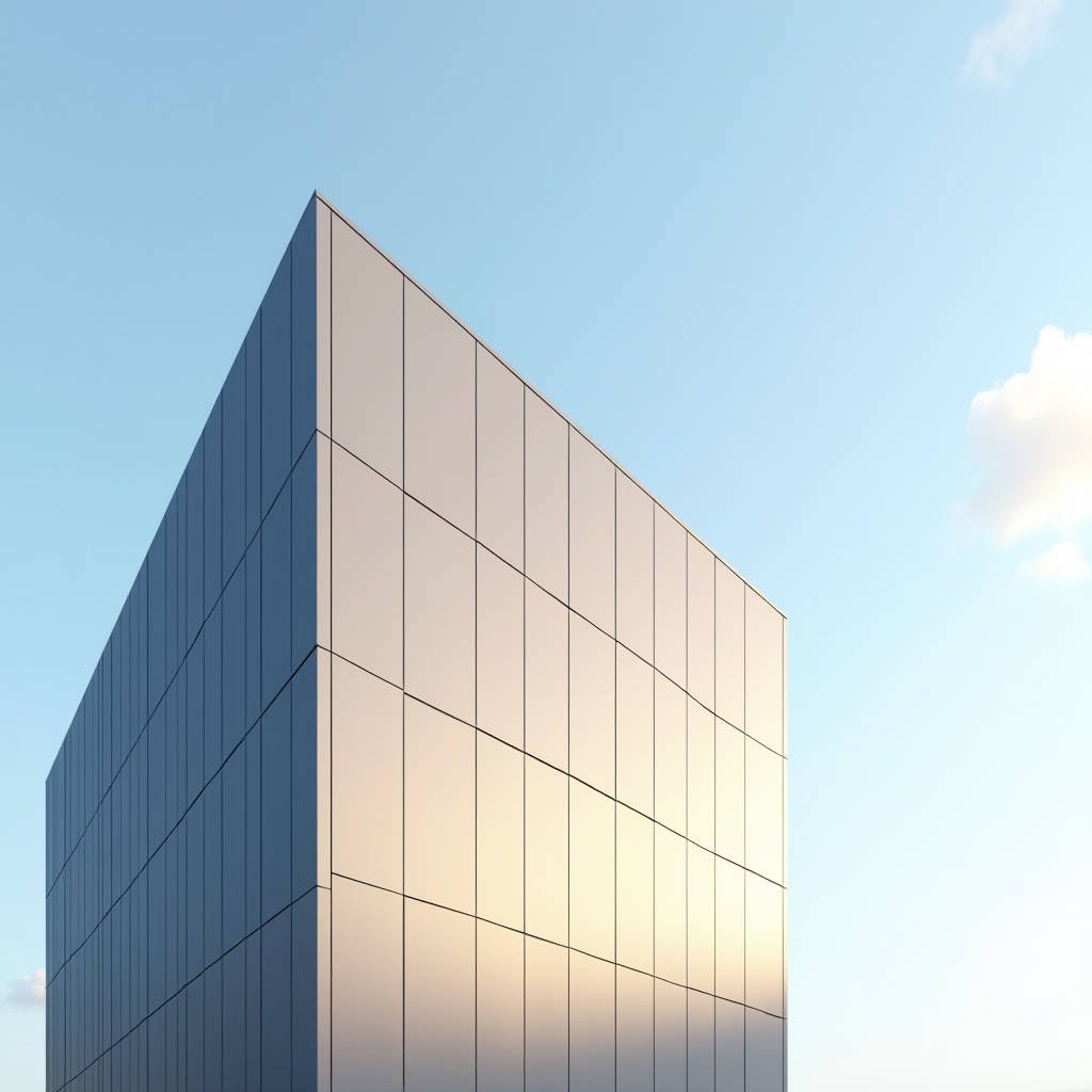
Every solid aluminium cladding panel on a high-rise facade expands and contracts with every degree of temperature change, and ignoring that movement is the fastest route to buckled joints, stressed fixings, and water ingress. Aluminum Alloy Thermal Expansion is not a theoretical footnote in a datasheet; it is a live force that dictates joint widths, bracket design, and even the choice of gasket material. For a 3000 mm panel spanning a sun-baked curtain wall, a 60 °C swing can produce roughly 4 mm of movement that must be absorbed by the system. This article walks through the governing coefficients, the calculation method, the practical joint and bracket consequences, and the coating and fabrication decisions that keep solid aluminium panels performing for decades.
Why the Coefficient Matters on Solid Panels
The linear thermal expansion coefficient of aluminium sits near 23 × 10⁻⁶ per °C, roughly twice that of steel and about three times that of glass. That number alone explains why a solid aluminium cladding system cannot be treated like a steel or glass assembly. The coefficient is not uniform across alloys; 6061-T6, 5052-H32, and 3003 each carry slightly different values, and the difference, though small, compounds over long panel runs.
For a facade engineer, the practical expression of this behaviour is the classic linear expansion formula:
ΔL = α × L₀ × ΔT
where ΔL is the change in length, α is the coefficient of linear thermal expansion, L₀ is the original length, and ΔT is the temperature change. A 2.5 mm thick 6061 panel at 3000 mm long, exposed to a 60 °C swing, moves about 4.1 mm. That is not a rounding error; it is a design input that shapes the entire support system.
Coefficient Values Across Common Alloys
Not every alloy expands identically, and the difference matters when a facade mixes alloys or when a panel is paired with a steel subframe. The table below summarises typical linear thermal expansion coefficients for alloys commonly used in solid cladding panels, based on published engineering data and the NIST reference work on aluminium alloy expansion.
| Alloy / Temper | CTE (×10⁻⁶ / °C) | CTE (×10⁻⁶ / °F) | Typical Cladding Use |
|---|---|---|---|
| 1100-O | 23.6 | 13.1 | Formed flashings, trim |
| 3003-H14 | 23.2 | 12.9 | General sheet, panels |
| 5052-H32 | 23.8 | 13.2 | Marine-adjacent, coastal facades |
| 6061-T6 | 23.6 | 13.1 | Structural panels, brackets |
| 5083-H116 | 23.4 | 13.0 | Heavy-duty, high-load panels |
The spread across these alloys is roughly 0.6 × 10⁻⁶ per °C. Over a 4000 mm panel and a 70 °C swing, that difference adds up to about 0.17 mm. Small on its own, but when a detail is designed to a 1 mm tolerance, alloy selection becomes a real decision rather than a paperwork exercise.
Calculating Movement for a Real Facade
To make the theory concrete, consider a 3000 mm long, 2.5 mm thick 6061-T6 solid panel in a temperate climate where the surface temperature swings from a winter low of −10 °C to a summer high of 70 °C. That is a ΔT of 80 °C. Using α = 23.6 × 10⁻⁶ / °C:
ΔL = 23.6 × 10⁻⁶ × 3000 × 80 = 5.66 mm
That is nearly 6 mm of movement across a single panel. Every connection, every hidden bracket, every sealant joint must accommodate that travel without transferring stress into the panel corners or the subframe. Designers who skip this calculation typically discover the problem after the first hot season, when panels begin to oil-can or when sealant joints start to tear.
For longer runs, the numbers grow quickly. A continuous 6000 mm panel with the same swing moves about 11.3 mm. This is why reputable facade systems break long runs into smaller panels and why expansion joints are placed at calculated intervals rather than at arbitrary column lines.
Joint Design and Sealant Limits
Once the movement is known, the joint width follows. A common rule is to leave a joint wide enough that the sealant only sees a fraction of its total strain capacity. A typical low-modulus silicone sealant can handle 25 to 50 percent movement, so a joint that must absorb 5.66 mm of movement needs a working width of roughly 12 to 20 mm, depending on the sealant specification and the installation temperature.
Installation temperature is a detail many site teams overlook. A joint installed at 20 °C in spring will behave differently from the same joint installed at 35 °C in late summer, because the panel is already partway through its expansion range. The sealant backer rod and the bond-breaker tape must be sized for the worst-case condition, not the day the panel was hung.
Bracket and Subframe Consequences
Solid aluminium panels are typically fixed to an aluminium or steel subframe with concealed brackets. Those brackets must allow the panel to slide relative to the subframe rather than fight it. A rigidly bolted panel will transfer thermal strain into the bracket legs, the screw threads, and eventually the panel edge, producing fatigue cracks over repeated thermal cycles.
Slotted holes, sliding cleats, and fixed-plus-free bracket patterns are the standard answers. The common practice is to fix one point rigidly and let every other point slide along the thermal axis. This gives the panel a defined expansion origin and prevents cumulative drift. The sliding surfaces should be separated by a nylon or PTFE washer to avoid galvanic corrosion between aluminium and steel and to keep the friction low enough that the panel moves freely.
Coating and Surface Effects on Heat Load
Surface temperature, not air temperature, drives the expansion. A dark PVDF-coated panel in direct sun can reach 70 to 80 °C on a day when the ambient air is only 35 °C. A light or metallic finish reflects more solar energy and stays cooler, reducing the ΔT and therefore the movement. This is a real design lever, not a marketing claim.
For a solid aluminium panel, the coating also affects the temperature gradient through the sheet. A 2.0 mm panel with a dark coating will reach a more uniform elevated temperature than a thicker 3.0 mm panel, which can develop a slight through-thickness gradient. In practice the effect is small, but it reinforces the point that coating colour and panel thickness are thermal inputs, not just aesthetic ones.
PVDF coatings, typically applied at 25 to 30 microns total film thickness over a primer, are the industry standard for exterior solid aluminium cladding because of their UV and weathering resistance. AAMA 2605 is the specification that governs the highest-performance exterior coatings, and it is worth specifying for any facade that must hold its colour and gloss for 20 years or more. The coating itself does not stop expansion, but choosing a proven system avoids the secondary failure of film cracking at panel edges where movement concentrates.
Fabrication Details That Reduce Stress
Fabrication geometry has a direct effect on how a panel handles thermal strain. Sharp internal corners concentrate stress and are the first place fatigue cracks appear after years of expansion and contraction. Radiused corners, deeper return flanges, and stiffening ribs all help distribute strain away from vulnerable points.
For large panels, a stiffening rib or a structural core can reduce oil-canning, which is the visible distortion that occurs when a large flat surface buckles under combined thermal and wind load. The rib does not change the coefficient of expansion, but it changes how the panel responds to the strain, keeping the surface flat and predictable.
When sourcing panels, a fabricator that controls alloy temper, sheet gauge, and edge radius consistently will produce panels that behave predictably under thermal load. A reliable supplier such as Futeng® maintains tight tolerances on 2.0, 2.5, and 3.0 mm solid aluminium sheet and documents the alloy and temper for every batch, so the expansion calculation in the design phase matches the panel delivered to site.
Designing for the Full Thermal Cycle
A facade does not experience a single temperature swing; it experiences thousands of cycles over its service life. Each cycle moves the panel, works the sealant, and flexes the brackets. Fatigue life, not just the peak movement, is the real design criterion. The joint and bracket system must survive these repeated cycles without the sealant losing adhesion or the screws loosening.
This is why the movement calculation should be done at both ends of the range, not just at the peak. A panel that is installed at 10 °C and then heated to 70 °C moves one way; the same panel cooled to −15 °C moves the other way. The joint must accommodate the full travel in both directions, and the fixed point must be chosen so the panel never slides off its bracket or into an adjacent panel.
Standards and References for the Engineer
Several references anchor the engineering decisions around thermal expansion in aluminium cladding. The NIST dataset on the thermal expansion of aluminium and its alloys provides the underlying coefficient values used in the table above. For coating performance, AAMA 2605 sets the benchmark for exterior PVDF finishes. For general aluminium alloy property data, the Aluminum Association's standards and the Engineering Toolbox reference tables are useful cross-checks when verifying a coefficient or a design formula.
- NIST thermal expansion data for aluminium alloys
- AAMA 2605 specification for exterior coatings
- Aluminum Association alloy standards
- Engineering Toolbox expansion reference tables
- ISO standards for aluminium and aluminium alloys
Practical Guidance for Procurement and Site
For the procurement team, the expansion behaviour of the panel is locked in by the alloy and gauge specified at tender stage. Changing the alloy late in the project changes the movement calculation and can invalidate the joint design. Specify the alloy, temper, and thickness clearly in the performance specification and require the fabricator to confirm them on every delivery certificate.
For the site team, the critical moments are the installation temperature and the joint installation. Record the ambient and panel surface temperature at the time of installation, and install the sealant at the temperature that the design assumed. If the panel is installed at the hot end of the range, the joint must be sized for the cold end, and vice versa. Skipping this step is the most common cause of premature sealant failure in solid aluminium cladding.
Finally, allow the panels to equalise with the site temperature before fixing. A panel that arrives cold from a warehouse and is bolted rigidly into a sun-heated frame will immediately begin to expand and will fight the fixings. A short acclimatisation period, even an hour in the shade, prevents a predictable and avoidable stress problem.
Aluminum Alloy Thermal Expansion is a design constant that never goes away, but it is a manageable one. With the right coefficient data, a clear movement calculation, a joint and bracket system built for the full thermal cycle, and a coating and fabrication standard that holds up over decades, a solid aluminium facade performs predictably from the first hot summer to the last cold winter. The panels will keep moving, but the system will keep absorbing it.