Aluminum Aerofoil Bracket Engineering Load Paths Corrosion Control and Angle Selection for Facade Sunshades
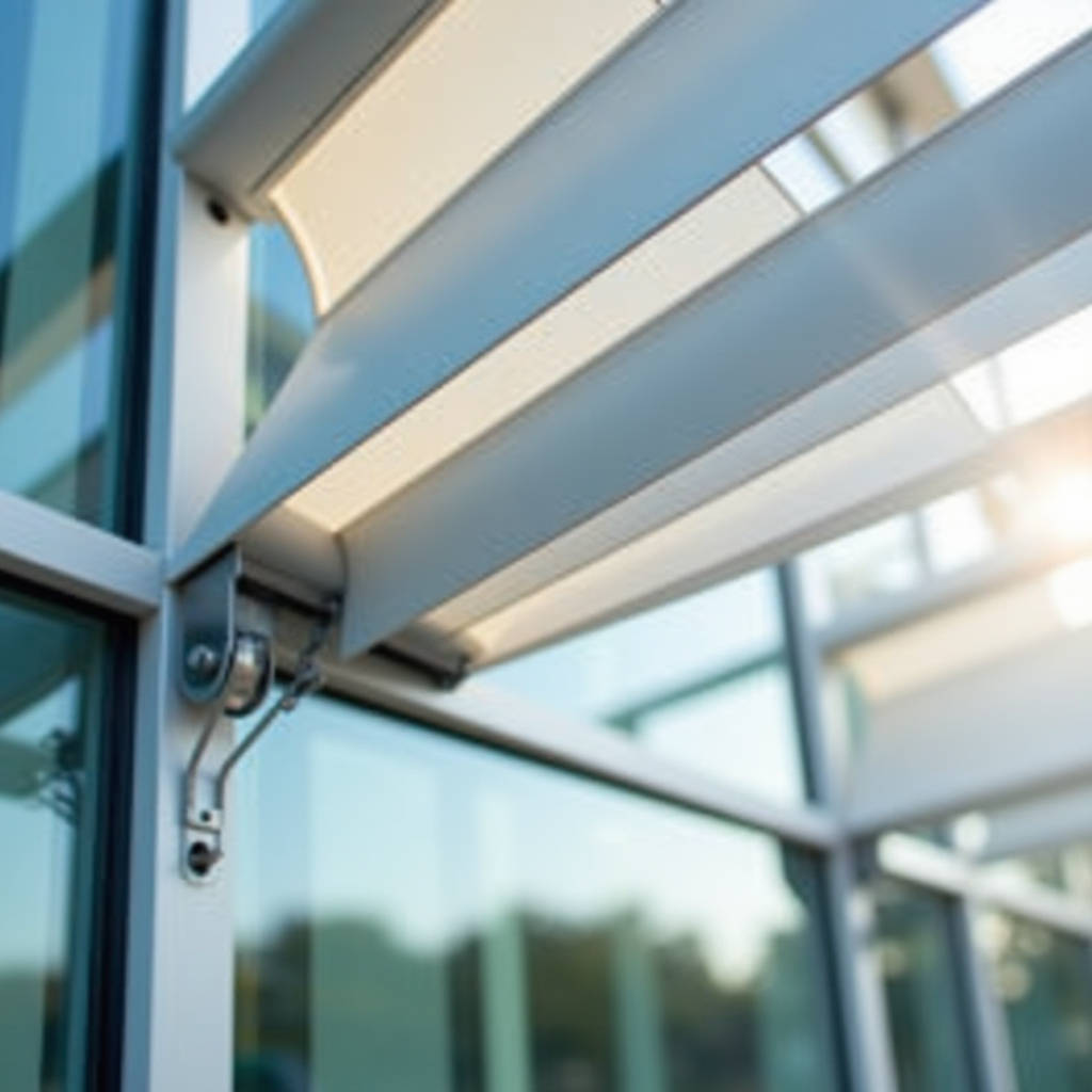
When specifying sunshade systems for commercial facades, the connection between blade and structure often determines whether a project meets its thermal performance targets or falls into costly remediation. The Aluminum Aerofoil Bracket sits at this exact intersection. It transfers wind loads from the blade surface to the primary structure, sets the blade angle that controls solar heat gain, and absorbs thermal expansion stresses that would otherwise warp the assembly. A bracket that looks adequate on a submittal drawing can fail in the field because the specifier overlooked three critical variables: load path continuity, galvanic isolation requirements, and the difference between adjustable and fixed-angle geometries. This article examines each of these variables through the lens of real project conditions, providing the engineering rationale that procurement teams and facade consultants need when evaluating bracket specifications for aluminum airfoil blade systems.
What Separates an Aluminum Aerofoil Bracket from Standard Mounting Hardware
A standard mounting bracket handles one primary function: it holds a component in place. An Aluminum Aerofoil Bracket handles four simultaneously: dead load support, wind load transfer, thermal movement accommodation, and angular positioning. The distinction matters because substituting generic hardware into an airfoil sunshade assembly creates failure modes that may not surface until the first seasonal temperature swing or high-wind event.
The bracket's geometry reflects its multi-role function. Most designs use a base plate that anchors to the building structure—either embedded channel, post-installed anchor, or direct steel connection—paired with a blade cradle that wraps around the extruded aluminum airfoil profile. Between these two elements sits the adjustment mechanism. On fixed-angle brackets, this is typically a serrated interface with 5-degree indexing increments. On operable brackets, a pivot pin and locking plate allow field adjustment, though the mechanism introduces additional points of potential loosening under cyclic loading.
The material specification for the bracket body itself warrants attention. While the blade is almost always 6063-T6 aluminum extrusion, the bracket may be fabricated from 6061-T6 aluminum plate, cast A356 aluminum, or even 304/316 stainless steel depending on the corrosion environment. When dissimilar metals contact, the bracket-to-structure interface becomes a galvanic cell. A well-designed Aluminum Aerofoil Bracket includes a thermal break pad or isolation shim at this junction—a detail that gets value-engineered out of too many projects.
Load Path Engineering: Wind, Dead Load, and Thermal Cycling
Facade engineers approach bracket design by tracing loads from the blade surface to the building structure. A 12-inch airfoil blade spanning 10 feet between brackets in a 110 mph wind zone (ASCE 7-16, Exposure Category B) generates approximately 28 psf design wind pressure on the projected area. For a single blade with 1.0 square foot of projected area per linear foot, each bracket must resist roughly 140 pounds of wind load in the worst-case direction. That number doubles when the blade angle approaches 45 degrees and the projected area increases.
Dead load calculations are simpler but equally important. A 12-inch extruded aluminum airfoil blade with a 0.125-inch wall thickness weighs approximately 3.2 pounds per linear foot. With brackets spaced at 10-foot centers, each bracket carries 16 pounds of dead load—a modest number that becomes significant when multiplied across hundreds of brackets on a large facade and combined with wind uplift forces that can reverse the load direction.
Thermal cycling introduces a load case that static calculations miss. Aluminum expands at approximately 0.0000129 inches per inch per degree Fahrenheit. A 20-foot blade length subjected to a 100°F temperature swing (from 20°F winter night to 120°F summer sun exposure) expands by roughly 0.31 inches. If the bracket connection restrains this movement, the resulting thermal stress can buckle the blade or fracture the bracket. Properly designed systems incorporate slotted connections or allow the blade to slide within the bracket cradle, accommodating movement without transferring stress to the anchors.
Wind Load Calculation Reference Table
| Blade Size (in) | Bracket Spacing (ft) | Wind Speed (mph) | Design Pressure (psf) | Load per Bracket (lbs) |
|---|---|---|---|---|
| 8 | 8 | 90 | 18.5 | 99 |
| 8 | 10 | 110 | 25.3 | 169 |
| 12 | 8 | 110 | 28.1 | 225 |
| 12 | 10 | 130 | 39.4 | 394 |
| 14 | 10 | 110 | 32.8 | 383 |
Note: Calculations assume ASCE 7-16 Exposure B, 33 ft mean roof height, solid blade surface. Actual values require project-specific engineering review.
Adjustable vs. Fixed-Angle Brackets: When Each Makes Sense
The choice between adjustable and fixed-angle brackets hinges on three project conditions: the precision of the as-built structure, the solar shading design intent, and the maintenance access strategy. Adjustable brackets, which typically offer angle settings from -35° to +35° in 5-degree increments, provide field flexibility that compensates for construction tolerances and allows fine-tuning of shading performance after installation. The trade-off is mechanical complexity and a higher per-unit cost.
Fixed-angle brackets, by contrast, are fabricated to a specific angle—commonly 0°, 30°, or 45°—and cannot be modified in the field. They cost less, have fewer parts that can loosen over time, and generally offer higher load capacity because the bracket geometry is optimized for a single load path. The risk is that if the supporting structure is out of tolerance by even a few degrees, the blade alignment will be visibly off, and correcting it requires shimming or bracket replacement.
A practical decision framework: projects with unitized curtain wall systems, where bracket attachment points are factory-located with tight tolerances, can confidently use fixed-angle brackets. Projects with cast-in-place concrete or field-welded steel supports, where as-built deviations of ±1/4 inch are common, benefit from adjustable brackets. The cost difference—roughly 30-50% more per bracket for adjustable versions—is often recovered through reduced field labor and elimination of rework.
Galvanic Corrosion and the Bracket-to-Structure Interface
Every Aluminum Aerofoil Bracket creates a junction where aluminum meets another material. When that material is carbon steel—the most common building structure—the galvanic potential difference is approximately 0.85 volts in the presence of an electrolyte. Rainwater, condensation, or coastal salt spray completes the circuit, and the aluminum (being anodic to steel) sacrifices itself. The corrosion concentrates at the contact interface, where it is least visible and most structurally dangerous.
The standard mitigation strategy follows AAMA guidelines: isolate the dissimilar metals with a non-conductive barrier. For bracket-to-steel connections, this means a 0.030-inch minimum thickness EPDM or neoprene isolation pad, plus non-conductive bushings around any stainless steel fasteners that pass through the aluminum bracket. Stainless steel fasteners themselves are cathodic to aluminum, so the bushing requirement applies regardless of the structural material.
Coastal and industrial environments demand additional measures. Within 3 miles of salt water, the bracket itself should be fabricated from 6061-T6 aluminum with a Class I anodized finish (AA-M12C22A31 per ASTM B580) or a minimum 3.0 mil PVDF coating. Some manufacturers, including Futeng®, offer bracket components with enhanced pretreatment processes that extend service life in aggressive environments. The incremental cost of these finishes—typically 15-25% of the bracket cost—is negligible compared to the expense of replacing corroded brackets on a completed building.
Bracket-to-Blade Attachment: Fastener Selection and Fatigue
The fasteners connecting the bracket to the airfoil blade operate under conditions that standard mechanical connections do not face: cyclic wind loading, thermal expansion and contraction, and vibration from building movement. A connection that relies solely on friction—such as a set screw bearing against the blade surface—will loosen over time as the aluminum expands and contracts. The correct approach uses a positive mechanical engagement: either a through-bolt that passes through both walls of the extrusion, or a bracket design that captures the blade profile mechanically.
Fastener material selection follows the same galvanic logic as the bracket-to-structure interface. The safest choice is 300-series stainless steel (304 for general use, 316 for coastal) with a nylon or PTFE isolation washer where the fastener head contacts the aluminum bracket surface. Thread-forming screws for aluminum should have a thread geometry designed specifically for the material—standard wood-thread or sheet metal screws strip the aluminum at installation torque levels that are far below the required clamping force.
Fatigue is the slow killer of bracket fasteners. A single 12-inch blade in a moderate wind zone experiences thousands of load cycles per year. Each cycle microscopically deforms the fastener and the surrounding aluminum. Over a 20-year design life, the cumulative damage can propagate a crack from a thread root. The engineering response is to specify fasteners with a fatigue endurance limit above the maximum cyclic stress, and to design the connection so that the fastener is loaded in shear rather than tension wherever possible. Shear-loaded connections distribute stress across the fastener cross-section rather than concentrating it at the thread engagement.
Coating Compatibility Between Bracket and Blade
A facade sunshade system presents a uniform visual appearance to the street, but the bracket and blade may arrive at the jobsite with different coating systems. The blade extrusion typically receives a factory-applied PVDF (polyvinylidene fluoride) coating meeting AAMA 2605, the highest-performance architectural coating standard with a 20-year film integrity warranty. The bracket, if it is fabricated from plate rather than extrusion, may receive a liquid-applied coating that does not match the blade's factory finish in gloss, color stability, or chalk resistance.
This mismatch creates a visible discontinuity that becomes more pronounced over time. The blade's PVDF coating retains its color and gloss for 15-20 years, while an inferior bracket coating may chalk and fade within 5-7 years. The solution is to specify that brackets receive the same coating system as the blades—either by sourcing brackets from the same coating line, or by requiring that bracket fabricators submit coating qualification documentation demonstrating equivalent performance to AAMA 2605.
Powder coating on brackets deserves specific scrutiny. Standard polyester powder coatings (AAMA 2603) offer adequate performance for interior applications but degrade rapidly under UV exposure. Super-durable polyester powders (AAMA 2604) provide intermediate performance suitable for sheltered exterior locations. Only PVDF liquid coatings or FEVE-based powder coatings meet AAMA 2605 requirements for full exterior exposure. The cost hierarchy is significant: AAMA 2603 powder adds roughly $2-4 per bracket, AAMA 2604 adds $5-8, and AAMA 2605 PVDF adds $10-18 per bracket depending on color and batch size.
Installation Sequence and Field Verification
The most carefully engineered Aluminum Aerofoil Bracket delivers zero value if installed incorrectly. The installation sequence begins with survey verification: the contractor must confirm that anchor locations on the structure match the bracket layout drawings within the specified tolerance, typically ±1/8 inch in both horizontal and vertical planes. Any deviation beyond this tolerance requires either slotted bracket holes (which reduce load capacity) or structural remediation.
Bracket installation proceeds from a fixed reference point outward. On a typical elevation, the installer sets the first bracket at one corner, verifies its position, then works along the horizontal line using a laser or string line to maintain alignment. Each bracket receives a torque verification on its anchor bolts—the specified torque value depends on anchor diameter and type, but a 1/2-inch diameter wedge anchor in 4,000 psi concrete typically requires 55-65 ft-lbs. Under-torqued anchors creep under sustained load; over-torqued anchors fracture the concrete.
Blade installation follows bracket installation and should proceed in a single direction to avoid accumulating tolerance errors. The installer inserts each blade into its bracket cradles, verifies the angle setting, and secures the blade-to-bracket fasteners. A final quality check confirms that all blades are parallel within the specified angular tolerance (typically ±1 degree) and that the blade alignment is visually straight when sighted along the elevation.
Bracket Type Comparison for Project Specification
| Parameter | Fixed-Angle Bracket | Adjustable Bracket | Operable Bracket |
|---|---|---|---|
| Angle Range | Single preset (0°, 30°, 45°) | -35° to +35° (5° increments) | 0° to 90° (continuous) |
| Relative Cost | Base (1.0x) | 1.3x - 1.5x | 2.0x - 2.8x |
| Load Capacity | Highest | Moderate | Lowest |
| Maintenance Requirement | Visual inspection only | Annual fastener check | Semi-annual mechanism service |
| Best Application | Unitized curtain wall, new build | Cast-in-place concrete, retrofit | Dynamic shading, high-performance facades |
| Typical Lead Time | 4-6 weeks | 5-7 weeks | 8-12 weeks |
Supply Chain Considerations for International Projects
Procurement teams managing international facade projects face a bracket supply chain that spans extrusion mills, fabrication shops, coating applicators, and hardware suppliers. The lead time for a custom Aluminum Aerofoil Bracket package typically ranges from 6 to 10 weeks, but this timeline assumes that all components are sourced from a single coordinated supply chain. When brackets are procured separately from blades, the risk of interface problems multiplies.
The extrusion profile for the blade determines the bracket's cradle geometry. If the bracket fabricator does not have access to the actual extrusion die drawings—or better, a physical sample of the blade profile—the bracket will not fit correctly. The gap may be too tight, preventing blade insertion, or too loose, allowing vibration and noise. The solution is to either source brackets and blades from a single supplier, or to require that the bracket fabricator receive a blade sample and verify fit before production.
For projects in the Middle East, Southeast Asia, and North America, regional certification requirements add another layer of complexity. Brackets installed in Dubai must comply with Dubai Municipality regulations and typically require ISO 9001 manufacturing certification. Projects in Florida's High Velocity Hurricane Zone require product approval with specific wind load testing per Florida Building Code. Suppliers serving these markets must maintain current certifications and provide documentation packages that satisfy local building department review.
Quality Verification: What to Inspect Before Shipment
A pre-shipment inspection of Aluminum Aerofoil Bracket components should verify dimensional accuracy, coating quality, and hardware completeness. The dimensional check uses a calibrated go/no-go gauge that matches the blade profile cross-section. The bracket must accept the gauge with a clearance of 0.015-0.030 inches—tight enough to prevent rattling, loose enough to allow thermal movement and installation tolerance.
Coating inspection follows ASTM D7091 for dry film thickness measurement. For PVDF coatings, the minimum total dry film thickness is 1.0 mil (25 microns) for a two-coat system and 1.5 mils (38 microns) for a three-coat system with primer. Individual measurements should not fall below 80% of the specified minimum. The inspector should also check for coating defects—pinholes, bubbles, orange peel, and color variation—using a visual comparison to an approved color range sample under standardized lighting conditions.
Hardware verification confirms that all fasteners, isolation pads, and bushings are present and match the submittal documentation. A common finding is that stainless steel fasteners have been substituted with zinc-plated steel without notification. The substitution may be discovered only when rust stains appear on the facade six months after installation. A simple magnet test during inspection identifies ferrous fasteners that should have been non-magnetic 300-series stainless steel.
Integrating Brackets into the Broader Facade System
The Aluminum Aerofoil Bracket does not exist in isolation. It connects to the building structure through anchors that must be coordinated with the facade's water management system. Every bracket penetration through the weather barrier creates a potential leak path. The correct detail includes a continuous sealant joint around the bracket base plate, integrated with the adjacent facade sealant system to maintain the drainage plane.
Thermal bridging is the other system-level concern. An aluminum bracket that passes directly from the exterior sunshade to the interior structure creates a conductive path that bypasses the facade insulation. In cold climates, this thermal bridge can drop the interior surface temperature below the dew point, causing condensation and mold growth. The solution is a thermal break—typically a fiberglass or polyamide component inserted between the exterior and interior portions of the bracket. The thermal break reduces heat flow by 60-80% compared to a continuous aluminum bracket, at a cost premium of approximately 20-30%.
For architects and facade consultants, the bracket represents a detail that deserves as much attention as the visible blade surface. A well-engineered bracket system, specified with proper corrosion protection, thermal isolation, and load capacity, ensures that the sunshade performs its energy-reduction function for the full service life of the building. The alternative—a bracket selected on price alone—may function adequately for the first year but will accumulate problems that become progressively more expensive to address as access becomes more difficult and warranty periods expire.
Engineering judgment applied at the bracket level prevents systemic facade failures. The bracket is the least visible component of a sunshade system and the one most likely to determine whether the system meets its design life.