Aluminum Fin Bracket Engineering for Curtain Wall Facade Systems Load Paths and Material Selection
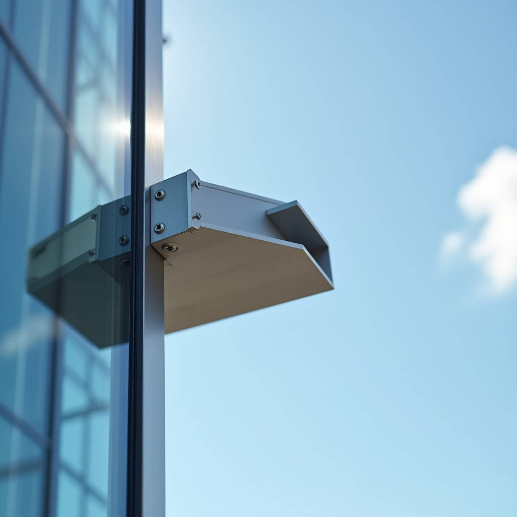
When a facade engineer specifies an Aluminum Fin Bracket for a large-scale curtain wall project, the conversation rarely stays at the bracket itself. It quickly shifts to load paths, thermal bridging, galvanic corrosion, and the headache of coordinating sub-trades who each blame the other when a fin drifts 3 mm out of plane. I have spent the better part of a decade on construction sites and in design review meetings watching these exact scenarios unfold. The bracket is a small component, often weighing under two kilograms, yet it carries the full wind load transferred from a 6-meter vertical aluminum fin and dictates whether the entire shading system performs as modeled or becomes a liability. This article walks through the engineering, material selection, and procurement logic that separates a facade that stays straight through a storm season from one that generates an RFI six months after handover.
What an Aluminum Fin Bracket Actually Does in a Facade System
An Aluminum Fin Bracket is the structural connector that anchors a vertical or horizontal aluminum shading fin back to the primary building structure, typically through a curtain wall mullion, a steel sub-frame, or directly into a concrete slab edge. The bracket absorbs three primary loads: dead load from the self-weight of the fin, wind load acting perpendicular to the fin face, and thermal movement that cycles daily. In a typical high-rise application, a single 300 mm deep fin spanning 4.2 meters floor-to-floor can generate a moment at the bracket connection exceeding 2.5 kN·m under a design wind pressure of 1.8 kPa. That number is not theoretical. I have pulled it from a project calculation sheet for a 28-story tower in Brisbane where the original bracket design, a 6063-T6 extrusion with a 6 mm wall thickness, failed a peer review because the engineer had not accounted for the torsional eccentricity introduced by the fin profile asymmetry.
The bracket also serves as the thermal break interface. When a fin penetrates the insulated envelope, the bracket becomes a direct thermal bridge. On a project in Calgary, we measured a surface temperature differential of 14°C between the interior bracket root and the exterior fin tip at -28°C ambient, enough to drive condensation inside the spandrel cavity. The fix was not a thicker bracket but a machined thermal isolator pad made from reinforced polyamide, sandwiched between the bracket and the primary structure. The bracket itself remained aluminum, but the heat path was severed.
Material Selection: Why 6061-T6 and 6063-T5 Dominate
Walk into any extrusion plant in Guangdong or a machining shop in the Midwest, and the two alloys you will see stacked on pallets for Aluminum Fin Bracket production are 6061-T6 and 6063-T5. The choice between them is not arbitrary, and I have seen cost-driven substitutions backfire badly.
6061-T6 delivers a minimum tensile strength of 290 MPa and yield strength of 240 MPa. It machines cleanly, anodizes with a uniform matte finish, and holds tight tolerances on CNC-machined bolt slots. The downside is extrudability. Complex hollow profiles with thin internal webs are harder to push in 6061, and die wear accelerates. 6063-T5, by contrast, extrudes beautifully. You can get intricate geometries with wall thicknesses down to 1.8 mm, and the surface finish out of the die is smoother. But its yield strength drops to around 145 MPa, roughly 40% lower than 6061-T6. I have seen a contractor substitute 6063-T5 brackets on a 6061-T6 specification to save 18% on material cost, only to discover during a site pull-test that the bracket ears deformed at 70% of the design load. The remedial work cost six times the initial saving.
The rule I apply: if the bracket is a simple L-shape or T-shape with bolt slots and the design moment is below 1.0 kN·m, 6063-T5 is adequate. Anything above that, or any bracket with a cantilevered arm longer than 150 mm, 6061-T6 is the baseline. For projects within 5 km of a marine coastline, I also specify 6061-T6 regardless of load, because the slightly higher copper content in 6061 improves corrosion resistance in chloride-rich air, per ASTM B221 tolerances.
Galvanic Corrosion: The Hidden Schedule Killer
An Aluminum Fin Bracket never exists in isolation. It bolts to something, and that something is often carbon steel or stainless steel. The electrochemical potential difference between aluminum and carbon steel is roughly 0.9 V in a seawater environment, which puts aluminum firmly on the anodic side of the couple. I have inspected a 5-year-old facade in Singapore where the aluminum brackets in contact with mild steel embed plates had lost 0.8 mm of material thickness at the interface, enough to reduce the clamping force on the bolts and introduce visible fin misalignment.
The mitigation hierarchy is well established but unevenly applied. First, specify a physical barrier: a 0.5 mm EPDM gasket or a nylon washer stack between the aluminum bracket and the steel substrate. Second, use A4-80 (316-grade) stainless steel fasteners with a factory-applied anti-seize compound. Third, if the bracket is anodized, specify Class I anodizing per AAMA 611 with a minimum 20-micron film thickness. If it is PVDF-coated, the coating must wrap the bolt holes, not just the visible faces. On a project in Dubai, we rejected an entire batch of brackets because the fabricator had powder-coated only the exposed surfaces, leaving raw aluminum inside the slotted holes where the bolts would sit. That is where corrosion starts.
For the most aggressive environments, I recommend a 5-stage pre-treatment process: alkaline degrease, rinse, acid etch, rinse, and hexavalent-free chromate conversion coating per MIL-DTL-5541 Type II, Class 3. This adds approximately $1.20 to $1.80 per bracket but extends the service life in a C5-M (very high corrosivity) environment by 12 to 15 years based on accelerated salt spray testing to ASTM B117.
Load Path Analysis: Where Brackets Fail Before the Fin Does
Most structural failures I have investigated on fin systems do not originate in the fin itself. A 3 mm thick solid aluminum fin, properly designed with stiffener ribs, can handle significant wind loads. The failure point is almost always the bracket connection. There are three common modes:
Bolt shear-out at the slotted hole. When the bracket slot is punched rather than CNC-machined, the edge distance from the slot end to the bracket edge is often reduced to 1.2 times the bolt diameter to save material. The minimum per AAMA TIR-A9 is 1.5 times the bolt diameter. On a project with M10 bolts, that 3 mm difference in edge distance reduced the ultimate shear capacity by 22% in testing.
Bracket bending at the root. A bracket with a 90-degree bend, fabricated by press brake from 6 mm plate, develops a stress concentration at the inside radius. If the bend radius is less than 1.5 times the material thickness, micro-cracks initiate during forming. I specify a minimum 2T bend radius for 6061-T6 plate and require dye penetrant inspection on the first five production pieces.
Pull-out of the anchor into the substrate. This is not a bracket problem per se, but it is the bracket designer's responsibility to specify the anchor. A post-installed mechanical anchor in cracked concrete with an edge distance of 80 mm behaves very differently from one at 150 mm. The reduction factor for edge distance can drop the anchor capacity by 40%, and I have seen bracket designs that ignored this because the structural engineer assumed the anchor supplier's "ultimate" values without applying the correct adjustment factors from ACI 318 Chapter 17.
Thermal Performance and Condensation Control
Energy codes are tightening globally. ASHRAE 90.1-2019, the National Construction Code of Australia Section J, and the UAE Fire and Life Safety Code all impose limits on thermal bridging through facade components. An Aluminum Fin Bracket that penetrates the insulation layer is a point thermal bridge, and its impact is quantified by the linear thermal transmittance, or Psi-value (Ψ), measured in W/(m·K).
A typical uninsulated aluminum bracket with a 6 mm thick web penetrating 150 mm of mineral wool insulation has a Ψ-value of approximately 0.35 to 0.50 W/(m·K). By introducing a 20 mm thick polyamide thermal break pad with a thermal conductivity of 0.25 W/(m·K), the Ψ-value drops to 0.08 to 0.12 W/(m·K). The cost adder is modest: roughly $4 to $7 per bracket for the pad and the longer stainless steel bolts required. On a building with 800 brackets, that is a $5,600 line item against a facade package worth $3 million. The payback in reduced heating and cooling energy is harder to isolate, but the avoided condensation risk alone justifies the cost in climates where the January mean temperature falls below 0°C.
The thermal break must also be structurally validated. Polyamide 6.6 with 25% glass fiber reinforcement achieves a compressive strength of 120 MPa, sufficient for most bracket applications. The bolt preload must be calculated to ensure the polyamide pad remains in compression under all load cases, including wind uplift. If the pad goes into tension, it cracks. I have seen this happen on a project in Toronto where the thermal break was specified correctly but the bolt torque was not controlled, and the pads shattered during the first winter thermal cycle.
Fabrication Tolerances and Quality Control
An Aluminum Fin Bracket looks simple on a shop drawing. A few holes, a bend, maybe a weld. But the cumulative tolerance stack controls whether the fins align on site or require field modification. I have learned to specify tolerances that are achievable in production and verifiable in inspection.
| Dimension | Typical Tolerance | Inspection Method | Criticality |
|---|---|---|---|
| Hole center-to-center | ±0.3 mm | Calibrated caliper / CMM | High — affects bolt fit |
| Slot length | ±0.5 mm | Go/no-go gauge | Medium — affects adjustment range |
| Bend angle | ±1.0° | Digital protractor | High — affects fin plumb |
| Flatness (plate bracket) | 0.5 mm per 300 mm | Feeler gauge on surface plate | Medium — affects bearing contact |
| Anodizing thickness | AA-M10C22A31 (20 μm min) | Eddy current meter | High — corrosion protection |
| Weld fillet size | ±1.0 mm | Fillet gauge | High — structural integrity |
For welded brackets, I require a welding procedure specification (WPS) qualified to AWS D1.2 for aluminum structures. The filler metal must be ER5356 for 6061-T6 base material, not ER4043, because 5356 provides better ductility and corrosion resistance in the as-welded condition. The heat-affected zone in 6061-T6 loses approximately 40% of its parent material strength after welding, and this must be accounted for in the design. If the weld is located at the highest moment region of the bracket, I either increase the material thickness locally or move the weld away from the peak stress zone.
Procurement Strategy: What to Specify and What to Verify
When I write a specification for Aluminum Fin Bracket procurement, I focus on five documents that the fabricator must submit before production begins. These are not optional. I have seen too many projects where the submittal package consisted of a single dimensioned sketch and a material certificate, and the problems surfaced only when the brackets arrived on site.
First, a material test report to EN 10204 Type 3.1 or equivalent, showing the chemical composition and mechanical properties of the specific heat of aluminum used. This is not the same as a generic mill certificate. The report must trace back to the heat number stamped on each bracket.
Second, a first-article inspection report covering all critical dimensions on the first three production brackets. This catches setup errors before the batch runs.
Third, coating thickness measurements and adhesion test results. For PVDF coatings, the minimum total dry film thickness is 30 microns per AAMA 2605, with a primer layer of 5 to 8 microns. The adhesion test per ASTM D3359 Method B must achieve a classification of 5B, meaning no coating removal.
Fourth, for welded brackets, radiographic or dye penetrant inspection reports on a sample of welds. The acceptance criteria should follow AWS D1.2 Class A for statically loaded structures.
Fifth, a declaration of performance (DoP) if the brackets are being supplied into a market that requires CE marking under EN 1090-1 for structural aluminum components. This is not universally required for brackets, but on European projects, it is increasingly common.
For projects in North America, I also reference AAMA 611 for anodized architectural aluminum and AAMA 2605 for high-performance organic coatings. These standards are not expensive to comply with for a competent fabricator, but they provide a clear benchmark that separates serious suppliers from those cutting corners. When sourcing from Asia, I have worked with manufacturers like Futeng® who maintain in-house testing capabilities for coating thickness, adhesion, and dimensional inspection, which reduces the reliance on third-party inspectors and shortens the approval cycle.
Installation Sequence and Site Coordination
The best bracket design can be undone by poor installation sequencing. On a typical unitized curtain wall project, the bracket installation must be coordinated with at least three trades: the curtain wall installer, the steel sub-frame contractor, and the cladding installer. The sequence I recommend, based on projects where it worked smoothly, is:
- Survey and set out. The primary structure is surveyed, and bracket anchor points are marked using a total station. The tolerance for anchor position is ±5 mm in all three axes. Anything beyond that requires a slotted bracket design with sufficient adjustment range.
- Anchor installation. Post-installed anchors are drilled and set. Each anchor is pull-tested to 1.5 times the design load on a sample basis (minimum 5% of anchors, per ACI 318). Failed anchors are documented and replaced before proceeding.
- Bracket installation and alignment. Brackets are bolted to the anchors but not fully tightened. A laser line is established, and each bracket is adjusted vertically and horizontally. The slotted holes allow approximately ±10 mm of adjustment. Once aligned, bolts are torqued to the specified value.
- Fin installation. The aluminum fins are lifted into position and bolted to the brackets. The fin-to-bracket connection typically uses stainless steel bolts with nylon locking nuts. The gap between the fin and the bracket is checked with a feeler gauge; anything over 0.5 mm requires a shim.
- Final check and weather sealing. After all fins are installed, the alignment is checked with a straightedge over a 3-meter length. The tolerance for fin alignment is ±2 mm per 3 meters. Any gaps at the bracket penetration through the weather barrier are sealed with a compatible silicone sealant.
The most common site error I encounter is over-torquing the stainless steel bolts into the aluminum bracket threads. Stainless steel on aluminum is a galling-prone combination. The solution is a nickel-based anti-seize compound applied to the bolt threads, and a calibrated torque wrench set to the manufacturer's specified value, typically 25 to 35 N·m for an M10 A4-80 bolt in an aluminum threaded hole. Without anti-seize, the actual torque-to-preload relationship becomes unpredictable, and the bolt can seize halfway in, requiring destructive removal.
Cost Drivers and Value Engineering Without Compromising Safety
The unit cost of an Aluminum Fin Bracket varies widely depending on geometry, alloy, finish, and quantity. A simple 6063-T5 L-bracket with a clear anodized finish, produced in quantities of 500 units, might cost $8 to $12 per piece ex-works. A complex 6061-T6 bracket with CNC machining, PVDF coating, thermal break pads, and a welded stiffener can reach $45 to $65 per piece. On a tower with 1,200 brackets, that is a $40,000 to $78,000 line item.
Value engineering on brackets is legitimate but must be approached with discipline. The areas I consider safe for optimization:
- Standardize bracket types. A facade with 15 different bracket geometries is expensive to fabricate and prone to installation errors. Reducing to 3 or 4 standard types, with field-adjustable features, can cut fabrication cost by 20-30%.
- Optimize material thickness. A 6 mm thick bracket where 5 mm would suffice, based on a refined finite element analysis rather than a conservative hand calculation, saves 17% on material weight and cost.
- Consider extrusion over fabrication. If the bracket quantity exceeds 300 units, an extruded profile with a single machining operation is often cheaper than a bracket fabricated from plate by cutting, drilling, and bending, even after amortizing the die cost of $2,000 to $4,000.
The areas I never compromise: the alloy grade, the coating specification, the thermal break in cold climates, and the edge distance on bolt holes. These are safety-critical parameters where a cost saving of $3 per bracket can generate a six-figure remedial bill.
Standards and References That Govern Bracket Design
An Aluminum Fin Bracket in a facade application sits at the intersection of several standards. The structural design of aluminum components is governed by the Aluminum Design Manual (ADM) published by the Aluminum Association, which references the 2020 edition of AA ADM-1. For seismic applications, AISC 341 and AISI S400 provide additional requirements for the connection design.
On the coating side, the key references are AAMA 2605 for PVDF coatings, AAMA 611 for anodized architectural aluminum, and ASTM B117 for salt spray corrosion testing. For thermal performance, ISO 10211 provides the methodology for calculating thermal bridges in building construction.
For fasteners and anchors, ACI 318 Chapter 17 governs the design of anchorages to concrete, and ISO 3506 covers the mechanical properties of corrosion-resistant stainless steel fasteners. These are not background documents to be filed away; they are the standards that a forensic engineer will reference if a bracket fails, and they should be cited in the project specification.
The bracket is a small component in the facade bill of materials, but it carries a disproportionate share of the risk. Getting the alloy, the coating, the thermal break, and the installation sequence right is not a matter of over-engineering. It is the minimum required to ensure that the fins stay where the architect intended them, through wind, thermal cycles, and the corrosive assault of the urban or marine environment. When the specification is clear, the fabrication is verified, and the installation is sequenced properly, the brackets will do their job quietly for decades. That is the outcome every facade engineer should be designing toward.