Aluminum Sunshade Support Engineering Load Paths Material Selection and Anchor Design for Exterior Shading
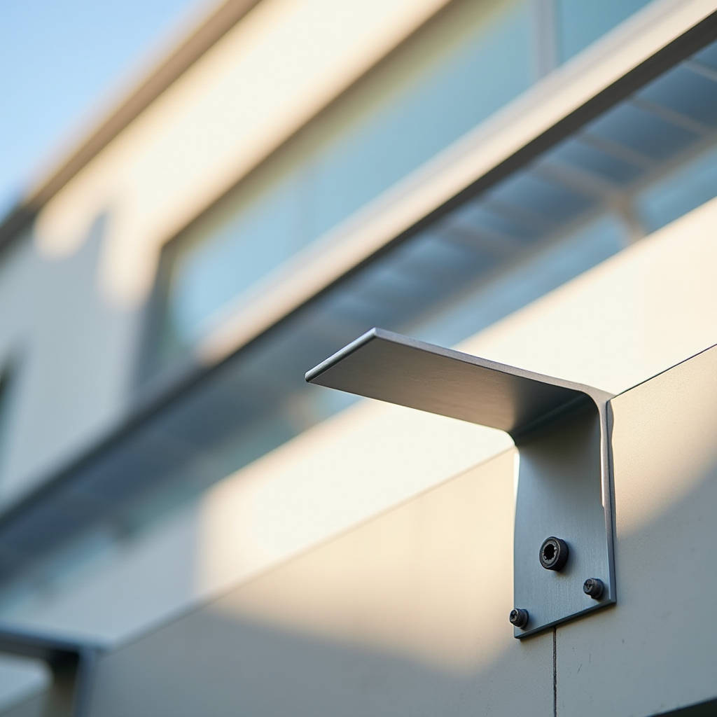
The structural integrity of an exterior shading system hinges on one component that rarely gets the attention it deserves: the Aluminum Sunshade Support. Architects spend months perfecting blade profiles, spacing ratios, and sightlines. General contractors track lead times for extruded airfoils. Yet when a sunshade assembly fails, the post-mortem almost never points to the blade itself. It points to the bracket, the anchor, the connection that transfers wind load from the aerodynamic surface back into the building substrate. The Aluminum Sunshade Support is not a commodity accessory. It is a load-path-critical element that demands the same rigor in material selection, finish specification, and thermal analysis as the visible shading members.
Why the Support Mechanism Defines the System
A horizontal aluminum sunshade projecting 900 mm from a curtain wall face generates substantial leverage. Under a 2.0 kPa wind load, a single outrigger bracket can experience a pull-out force exceeding 8 kN at the top anchor. The Aluminum Sunshade Support must handle this without yielding, without creeping, and without transferring unacceptable deflection into the glazing system. When specifying solid aluminum cladding panels as integrated shading elements, the support connection becomes even more critical because panel weight adds dead load to an already stressed assembly.
Three failure modes dominate the warranty claims landscape. First, galvanic corrosion at the stainless steel-to-aluminum interface when isolation is omitted. Second, fatigue cracking at the weld between the bracket body and the mounting plate, accelerated by thermal cycling. Third, concrete spalling at embed locations where water ingress follows the anchor bolt path. Each of these failures traces back to decisions made during the support design phase, not the blade fabrication phase.
Material Selection for Load-Bearing Support Components
Not all aluminum is equal when it comes to structural support duty. The Aluminum Sunshade Support bracket typically demands 6061-T6 or 6082-T6 alloy, both offering tensile strengths above 260 MPa after heat treatment. This contrasts with the 6063-T5 or 6063-T6 often used for non-structural blade profiles, where extrudability and surface finish take priority over strength. The difference matters: a 6061-T6 bracket can carry roughly 40% more bending moment than an identically sized 6063-T5 component.
For projects in coastal environments, alloy selection intersects with corrosion resistance. The 5xxx series marine-grade aluminum offers superior salt-spray performance but cannot be heat-treated to the same strength levels as 6xxx alloys. The engineering compromise often involves 6061-T6 with a marine-grade PVDF coating system applied after machining, ensuring that drilled holes and cut edges receive protection. Futeng® has supplied Aluminum Sunshade Support components for multiple high-rise projects in Southeast Asian coastal cities, where the combination of 6061-T6 substrate and 70% PVDF fluoropolymer coating has demonstrated zero structural degradation after five years of monsoon exposure.
Thermal Bridging and the Support Connection
The Aluminum Sunshade Support creates a direct thermal bridge from the exterior shading element into the building envelope. A continuous aluminum bracket penetrating the insulation layer can reduce the effective R-value of a wall assembly by 15-25% at each attachment point, depending on bracket geometry and fastener density. This is not a theoretical concern. ASHRAE 90.1 and the International Energy Conservation Code now require thermal break strategies for cantilevered exterior attachments in many climate zones.
Three thermal isolation approaches have gained traction. The first uses a fiberglass-reinforced polyamide thermal break pad inserted between the aluminum bracket and the structural substrate, reducing conductive heat transfer by approximately 85% compared to direct metal-to-metal contact. The second approach employs a proprietary structural thermal break module cast into the concrete slab edge, isolating the entire anchor assembly. The third, used primarily in retrofit applications, mounts the Aluminum Sunshade Support on standoff brackets that create an air gap between the support and the wall face, allowing continuous insulation to pass behind the attachment point.
The cost implications are real. A thermal break pad adds $12-18 per attachment point. For a building with 400 sunshade brackets, that represents $4,800-7,200 in additional material cost. Set against the energy penalty of unbroken thermal bridges over a 30-year building lifespan, the payback period typically falls under three years in heating-dominated climates and under five years in cooling-dominated climates.
Anchor Engineering: Embed Plates, Through-Bolts, and Post-Installed Systems
The Aluminum Sunshade Support must ultimately connect to something. In cast-in-place concrete construction, the preferred method is a stainless steel embed plate with headed studs, cast flush with the concrete surface. The aluminum support bracket then bolts to the embedded plate, with a 2 mm EPDM isolation gasket preventing direct aluminum-to-steel contact. This approach distributes the reaction forces across multiple studs and provides adjustment tolerance in three axes during installation.
Post-installed anchors become necessary when embeds are misplaced or when attaching to existing structures. Adhesive anchors using epoxy or hybrid polymer systems offer pull-out capacities exceeding 40 kN in uncracked concrete when properly installed. However, the installation quality variables are significant: hole cleaning, moisture content, concrete temperature during curing, and installer technique all influence the achieved capacity. The ASTM E488 standard governs testing methods for these anchors, and specifying proof-load testing on 10% of installed anchors has become standard practice on institutional projects.
Through-bolt connections, where the Aluminum Sunshade Support bracket bolts through the full thickness of a concrete slab or steel beam, provide the most predictable load path. The bolt sees double shear, the concrete or steel web resists bearing, and the connection can be inspected from both sides. The trade-off is aesthetic: bolt heads are visible on the interior face, which may conflict with architectural intent in occupied spaces.
Finish Durability on Support Hardware
The support bracket operates in a harsher micro-environment than the shading blade. Water running down the blade surface collects at the bracket junction, creating a persistent wet condition. Debris accumulates in the corner where the bracket meets the wall. Cleaning access is limited because the bracket sits behind the blade assembly. These conditions demand a finish specification that exceeds what would be adequate for the visible blade surfaces.
AAMA 2605-compliant PVDF coatings remain the benchmark for Aluminum Sunshade Support components in architectural applications. The 70% PVDF resin system, applied at a minimum dry film thickness of 30 microns over a chrome-phosphate conversion coating, provides the combination of UV resistance, chemical resistance, and flexibility needed for a component that experiences both weathering and mechanical stress. Below is a comparison of common finish systems for aluminum support components:
| Finish System | Standard | DFT (microns) | Salt Spray Resistance | Relative Cost | Typical Application |
|---|---|---|---|---|---|
| PVDF 70% (3-Coat) | AAMA 2605 | 30-40 | 4,000+ hours | 100% (Baseline) | Premium architectural, coastal |
| PVDF 50% (2-Coat) | AAMA 2604 | 25-30 | 3,000 hours | 75-80% | Mid-range commercial |
| Polyester Powder Coat | AAMA 2603 | 60-80 | 1,000 hours | 50-60% | Interior or sheltered exterior |
| Anodized (Class I) | AA-M10C22A31 | 15-20 | 1,500 hours | 85-95% | Interior, low-pollution exterior |
| Fluoropolymer Powder | AAMA 2605 | 50-70 | 4,000+ hours | 110-120% | High-durability, edge-critical |
The cost premium for AAMA 2605 over 2604 on support brackets is modest in absolute terms because the bracket surface area is small relative to the blade area. On a typical project, upgrading the support finish adds less than 1% to the total sunshade package cost while eliminating the risk of bracket corrosion that would require blade removal to access for remediation.
Fabrication Tolerances and Installation Sequencing
The Aluminum Sunshade Support must accommodate cumulative dimensional variation from three sources: the building structure, the curtain wall or cladding system, and the sunshade assembly itself. Concrete tolerances of ±13 mm in slab edge location are common per ACI 117. Curtain wall anchor channels add another ±3 mm. If the sunshade bracket provides no adjustment, the blade alignment will be visibly irregular, and the architect will reject the installation.
Slotted connections in the Aluminum Sunshade Support bracket provide ±10 mm of vertical adjustment and ±15 mm of horizontal adjustment when properly designed. Serrated or toothed interfaces between the bracket and the mounting plate prevent slippage after tightening, maintaining the adjusted position under cyclic wind loading. Some manufacturers now offer three-axis adjustable brackets with spherical washers that accommodate angular misalignment up to 3 degrees, which is particularly valuable when the support attaches to a sloped or curved facade surface.
Installation sequencing matters. The support brackets should be installed and surveyed before the sunshade blades are lifted into position. A common mistake is to install blades immediately after brackets, only to discover that accumulated tolerance errors have shifted the blade alignment. The correct sequence: install brackets, survey and adjust, torque all fasteners to specification, install blades, perform final alignment check. Rushing this process has led to costly rework on projects where blade removal required partial dismantling of adjacent cladding panels.
Wind Load Considerations and Code Compliance
The Aluminum Sunshade Support is a component and cladding element under ASCE 7, meaning it must be designed for the higher wind pressures applicable to small-area elements rather than the lower pressures used for main wind force resisting systems. A sunshade blade projecting from a building corner experiences wind pressures 1.5 to 2.5 times higher than the same blade at mid-facade, due to flow acceleration around the building edge. The support bracket at the corner location must be sized accordingly.
Wind tunnel testing provides project-specific pressure coefficients that often reduce the conservatism built into the ASCE 7 analytical method. For buildings over 60 meters in height or with unusual geometries, the investment in wind tunnel testing typically pays for itself through reduced bracket sizes and anchor quantities. The ASCE 7-22 standard includes updated provisions for canopy and attached element loading that reflect recent research on vortex shedding and buffeting effects.
Fatigue from wind-induced vibration is a separate concern from static strength. Aluminum sunshade blades can vibrate at frequencies between 2 and 10 Hz under certain wind conditions, and the support bracket experiences the full cyclic stress at the connection point. The endurance limit for 6061-T6 aluminum is approximately 97 MPa at 5×10⁸ cycles. Bracket designs that keep peak cyclic stress below 50% of this limit, achieved through adequate section modulus and attention to stress concentration at geometry changes, have demonstrated trouble-free service lives exceeding 30 years.
Integration with Solid Aluminum Cladding Panel Systems
When the Aluminum Sunshade Support penetrates through a solid aluminum cladding panel facade, the waterproofing detail at the penetration becomes critical. A 3.0 mm solid aluminum panel, unlike a thin composite skin, has sufficient structural capacity to carry the bracket reaction directly, provided the panel stiffener layout is coordinated with the bracket attachment points. The preferred approach uses a sub-frame behind the panel that transfers bracket loads to the building structure independently of the cladding panel, with the panel then sealed around the bracket penetration using a compression gasket and silicone weather seal.
The alternative approach, where the bracket bolts through the cladding panel into structure behind, requires careful detailing of the panel opening. The hole in the panel must be oversized to accommodate differential thermal movement between the bracket (attached to structure) and the panel (attached to its own framing system). A 6 mm annular gap around the bracket, filled with a low-modulus silicone sealant, accommodates the expected differential movement on a 3-meter panel span across a 50°C temperature range.
For projects using solid aluminum panels as integrated shading elements, where the panel itself extends beyond the facade plane to provide shading, the support design must address the panel's own structural behavior. A 2.5 mm solid aluminum panel with a 600 mm cantilever requires intermediate stiffeners to prevent oil-canning and flutter. The support connection at the panel-to-structure interface must resist both the panel dead load and the wind load on the cantilevered portion, typically requiring a bracket spacing of 600-900 mm depending on the cantilever length and wind zone.
Quality Control and Testing Protocols
Fabrication quality control for the Aluminum Sunshade Support should include weld inspection, dimensional verification, and finish testing. Welds on structural brackets should receive 100% visual inspection per AWS D1.2, with dye penetrant or radiographic testing on a sampling basis for critical joints. Dimensional verification should confirm that slotted hole positions, bracket angles, and mounting plate flatness are within the specified tolerances before the brackets leave the fabrication shop.
Pre-installation mock-up testing provides the most reliable validation of the entire support system. A full-scale mock-up including the building substrate, waterproofing, bracket assembly, and a representative section of sunshade blades should be subjected to static load testing at 1.5 times the design wind pressure. The mock-up should also undergo a water spray test to verify the weather seal at the bracket penetration. The cost of a mock-up, typically $8,000-15,000, is a fraction of the cost of remediating a systemic failure discovered after full installation.
On-site pull-out testing of installed anchors, using a calibrated hydraulic test rig, confirms that the as-installed anchor capacity meets or exceeds the design requirement. Testing 5% of anchors, with a minimum of three per anchor type, is a reasonable specification. The test load should reach 1.25 times the design load without displacement exceeding 3 mm, per the recommendations in AAMA TIR-A14.
Cost Drivers and Value Engineering
The Aluminum Sunshade Support typically represents 15-25% of the total sunshade system cost, varying with bracket complexity, finish specification, and anchor type. When value engineering pressure arises, the support system is often targeted for cost reduction because it is less visible than the blades. This is a false economy. Reducing bracket section, eliminating thermal breaks, or downgrading the finish saves a small percentage of the total package cost while introducing disproportionate risk.
A more productive value engineering approach examines bracket spacing optimization. Increasing bracket spacing from 900 mm to 1,200 mm reduces the bracket count by 25%, but requires a corresponding increase in blade section to span the longer distance. The net savings depend on the relative cost of blade extrusion versus bracket fabrication. On projects where the blade is a simple rectangular hollow section and the bracket is a complex welded assembly, the wider spacing often yields net savings. Where the blade is a custom airfoil extrusion, the increased blade cost may outweigh the bracket savings.
Another VE opportunity lies in anchor consolidation. Designing the Aluminum Sunshade Support to share anchor points with curtain wall mullion connections or cladding sub-frame attachments eliminates redundant embed plates and reduces the number of penetrations through the waterproofing layer. This requires early coordination between the sunshade engineer and the facade consultant, ideally during the design development phase rather than during shop drawing review.
The long-term cost of ownership argument favors robust support design. A sunshade support failure requires blade removal, possibly scaffold erection, bracket replacement, and reinstatement of waterproofing. The direct cost of such a repair, even for a single bracket, can exceed $3,000. The indirect costs from disrupted building operations and water damage are often far higher. Investing in proper material selection, finish specification, and installation quality at the outset is the most cost-effective strategy over the building's service life.
Specifying the Aluminum Sunshade Support with the same attention to detail as the visible architectural elements is not over-engineering. It is a recognition that the hidden components carry the load, resist the corrosion, and determine whether the system performs for 10 years or 50 years. The bracket is not an afterthought. It is the foundation of a durable exterior shading solution.