Aluminum Louver Bracket Specification for Commercial Facade Load Path and Corrosion Resistance
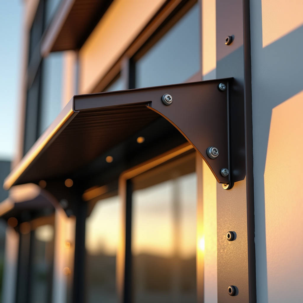
When a facade contractor calls at 7 a.m. asking why a louver system failed six months after handover, the conversation rarely starts with the blade. It starts with the bracket. The aluminum louver bracket sits at the intersection of dead load, wind load, thermal movement, and galvanic corrosion — four forces that operate simultaneously and without mercy. Get the bracket specification wrong, and the entire louver assembly becomes a liability. This article examines what actually determines bracket performance in commercial facades: alloy selection, coating compatibility, fastener isolation, and the load-path calculations that separate a 5-year installation from a 25-year one.
What an Aluminum Louver Bracket Actually Does
An aluminum louver bracket is not just a connector. It is the structural node that transfers every force acting on the louver blade — gravity, wind pressure, thermal expansion, and occasional impact — back into the building's primary structure. In a typical commercial facade, a single bracket might carry 15 to 40 kg of static load per linear meter, depending on blade depth, spacing, and material thickness. When wind loads enter the equation, the numbers shift dramatically. A 150 km/h wind gust on a 200 mm deep louver blade generates roughly 0.85 kN/m² of pressure. Multiply that across a 3-meter span, and the bracket pair at each support point is handling over 2.5 kN of combined load. That load path runs through the bracket body, into the fasteners, and finally into the subframe. Every material choice along that chain matters.
The bracket also controls blade angle. In fixed-louver installations, the bracket's geometry determines whether rainwater drains away from the building or pools against the gasket line. In operable systems, bracket tolerances directly affect how smoothly the linkage mechanism operates after 10,000 cycles. These are not academic concerns. They show up in punch lists, warranty claims, and eventually, in the reputation of the contractor who specified them.
Alloy Selection: Why 5052 and 6063-T5 Dominate
Not all aluminum is interchangeable. The two alloys that dominate commercial louver bracket manufacturing are 5052-H32 and 6063-T5, and they serve different purposes. 5052 is a magnesium-rich alloy with excellent corrosion resistance and formability. It bends without cracking, which makes it the preferred choice for brackets that require folding or complex geometries. Its tensile strength sits around 228 MPa, with yield strength at 193 MPa. 6063-T5, by contrast, is an extrusion-grade alloy with slightly lower corrosion resistance but superior dimensional stability. It machines cleanly and holds tight tolerances, which matters when brackets must align across dozens of mullions.
The practical distinction: a contractor building a coastal project in Southeast Asia should lean toward 5052 for its chloride resistance. A contractor fabricating a geometrically complex louver system for a data center facade in Frankfurt might choose 6063-T5 for its machinability and consistent section profiles. Both alloys work. The failure mode comes when someone substitutes a generic 3003 or 1100 alloy to save cost — those materials lack the strength and corrosion resistance for exterior facade applications.
| Property | 5052-H32 | 6063-T5 | 3003-H14 (Not Recommended) |
|---|---|---|---|
| Tensile Strength (MPa) | 228 | 186 | 152 |
| Yield Strength (MPa) | 193 | 145 | 131 |
| Corrosion Resistance | Excellent (marine grade) | Good | Moderate |
| Formability | Excellent | Moderate | Excellent |
| Typical Application | Coastal facades, folded brackets | Extruded profiles, tight tolerances | Interior only |
| ASTM Standard | ASTM B209 | ASTM B221 | ASTM B209 |
Galvanic Corrosion: The Hidden Bracket Killer
Here is a scenario that repeats across markets: a contractor installs aluminum louver brackets with stainless steel fasteners, assumes the combination is corrosion-proof, and then discovers white oxide blooms around every bolt hole within 18 months. The problem is galvanic corrosion. Aluminum and stainless steel sit about 0.5 to 0.6 volts apart on the galvanic series in most atmospheric conditions. When an electrolyte — rainwater, coastal spray, or even high-humidity condensation — bridges the two metals, the aluminum becomes the anode and corrodes sacrificially.
The fix is not to avoid stainless steel fasteners. Stainless steel (304 or 316 grade) is still the correct choice for structural fasteners in facade applications. The fix is isolation. Every fastener that passes through an aluminum louver bracket needs a nylon or EPDM isolation washer between the screw head and the bracket surface. For through-bolt applications, a nylon sleeve or bushing inside the hole prevents edge contact. The AAMA 2605 and 2604 coating specifications address the aluminum surface, but they do not replace mechanical isolation at the fastener interface.
In projects within 5 km of a coastline, the specification tightens further. Fasteners should be 316 stainless steel minimum, and the bracket itself should carry a marine-grade PVDF coating with a minimum 35-micron dry film thickness. Some manufacturers, including Futeng®, offer bracketry pre-coated with a 3-coat PVDF system that matches the louver blade finish exactly, eliminating the aesthetic mismatch that often occurs when brackets are sourced separately from blades.
Thermal Movement: Why Rigid Brackets Crack Facades
Aluminum expands at roughly 23 microns per meter per degree Celsius. On a 3-meter louver span subjected to a 50°C temperature swing between winter night and summer afternoon, that translates to approximately 3.45 mm of linear movement. If the bracket connection is fully rigid — no slotted holes, no expansion allowance — that movement converts directly into stress at the fastener points. Over several seasonal cycles, the aluminum around the bolt holes work-hardens, develops micro-cracks, and eventually fails.
The engineering solution is slotted connections. One bracket in each pair should have round holes for fixed positioning; the other should have horizontally slotted holes that allow the blade assembly to expand and contract freely. The slot length should be calculated based on the maximum expected temperature delta for the project location, not a generic rule of thumb. A project in Riyadh (70°C annual delta) needs more slot travel than one in London (40°C delta).
This is not a cost issue. The slotting adds negligible fabrication cost. It is a design discipline issue. Contractors who skip this detail end up with cracked blades, sheared fasteners, or deformed brackets — all of which are far more expensive to remediate than specifying the slot correctly from the start.
Load Path Analysis: What the Numbers Actually Say
A properly specified aluminum louver bracket must handle three distinct load cases. First, dead load: the self-weight of the louver blades plus any accumulated debris or ice. Second, wind load: calculated per the project's local building code, typically ASCE 7 in North America or EN 1991-1-4 in Europe. Third, maintenance load: a 1.0 kN point load applied at the most unfavorable position, representing a worker leaning on or stepping near the louver during cleaning.
For a typical 200 mm deep x 3,000 mm long aluminum louver blade at 150 mm spacing, the dead load per blade is approximately 4.8 kg (assuming 2.5 mm wall thickness). With brackets at 1,000 mm centers, each bracket pair supports three blades — roughly 14.4 kg static. Add wind load at 1.2 kPa (basic wind speed of 160 km/h, exposure category B), and the bending moment at the bracket root becomes the governing design case. A bracket fabricated from 4 mm thick 5052-H32 aluminum with a 60 mm wide base typically handles this with a safety factor above 2.0, but the calculation must be verified per project.
The Aluminum Association publishes design manuals that provide allowable stress values for common alloys and tempers. These values, combined with the project-specific load cases, form the basis of any legitimate bracket specification. A supplier who cannot provide load tables or calculation reports for their brackets is not a supplier worth engaging.
Coating Compatibility Across the Assembly
The bracket's coating must match the louver blade's coating — not just in color, but in chemistry. Mixing coating systems creates two problems. First, differential weathering: a PVDF-coated blade next to a powder-coated bracket will fade at different rates, and within three years the color mismatch becomes visible from street level. Second, and more critically, some powder coatings lack the flexibility to handle the micro-movements at the bracket-blade interface, leading to cracking and moisture ingress.
The industry standard for high-end commercial facades is a 3-coat PVDF system meeting AAMA 2605 specifications. This system includes a primer coat for adhesion, a color coat with 70% minimum PVDF resin content, and a clear top coat for UV protection. Total dry film thickness should be 30-35 microns minimum. For projects in aggressive environments — industrial zones with high SO₂ levels, coastal areas with salt spray — a 4-coat system with an additional barrier primer is worth the incremental cost.
Anodized brackets are an alternative, particularly for interior or protected exterior applications. Type II anodizing (10-15 microns) is adequate for indoor use. Type III hard anodizing (25-50 microns) provides better abrasion resistance but can exhibit color variation across batches. The key decision point: anodized finishes do not offer the same UV resistance as PVDF, so they are generally unsuitable for south-facing facades in high-sun regions.
Bracket Geometry and Water Management
The shape of an aluminum louver bracket affects more than structural performance. It directly controls how water behaves on the facade. A well-designed bracket includes a drip edge — a small downward projection at the outermost point — that forces water to detach and fall clear of the building face. Without a drip edge, surface tension pulls water around the bracket and onto the subframe, where it can penetrate sealant joints and cause concealed corrosion.
Bracket geometry also determines the blade's drainage angle. Most fixed louver systems specify a blade angle between 35° and 45° from horizontal. At 35°, water runs off efficiently while still providing reasonable visual screening. At 45°, screening improves but water may splash back onto the blade above. The bracket's mounting slot position must be calculated to achieve the specified angle with the actual blade profile being used — a 200 mm blade from one extruder may have a different center of gravity than a 200 mm blade from another, and the bracket pivot point must account for this.
For operable louver systems, bracket tolerances tighten considerably. The pivot hole diameter should be controlled to ±0.1 mm to prevent slop in the linkage mechanism. The linkage arm attachment point must be positioned to within ±0.5 mm of the design location, or the entire bank of louvers will operate unevenly. These are machining tolerances, not fabrication tolerances, and they require CNC equipment rather than manual drilling.
Installation Sequence and Common Errors
Even a perfectly specified bracket fails if installed incorrectly. The most common error is over-torquing fasteners. Aluminum brackets deform under excessive clamping force, and once the bracket base is bowed, the load distribution changes from uniform bearing to point loading at the edges. The result is premature fatigue cracking. The correct torque for an M8 stainless steel bolt into an aluminum bracket with an isolation washer is typically 15-18 N·m — far less than what a worker with an impact driver will instinctively apply.
The second common error is mixing metals in the subframe connection. If the building's primary structure is steel, the interface between the steel subframe and the aluminum bracket requires a full isolation gasket, not just washers at the bolt holes. A 1 mm thick EPDM or neoprene gasket across the entire contact area prevents the galvanic cell that would otherwise form.
The third error is installing brackets without verifying substrate flatness. A bracket bolted to an uneven steel channel will distort as the bolts are tightened, pre-stressing the aluminum and reducing its fatigue life. The substrate should be checked with a straight edge before bracket installation, and shims should be used to correct deviations greater than 2 mm over the bracket's base length.
Specifying for Seismic and High-Wind Zones
In seismic zones (IBC Seismic Design Categories D, E, and F), the bracket specification must account for inter-story drift. The louver assembly must accommodate the building's expected lateral displacement without shedding components. This typically requires brackets with oversized slotted connections in the horizontal direction and a positive retention mechanism — a shouldered bushing or a captive washer — that prevents the bracket from disengaging from the slot even if the fastener loosens during a seismic event.
In high-wind zones (hurricane-prone regions per ASCE 7), the governing load case shifts from bending to pull-out. The fasteners connecting the bracket to the subframe must be designed for tension, not just shear. This often means specifying longer fasteners with deeper embedment, or switching from self-tapping screws to through-bolts with backing plates. The bracket itself may need to be upsized — a 6 mm thick base plate instead of 4 mm — to handle the increased bending moment at the fastener line.
The ASTM E330 test standard for structural performance of exterior windows, doors, and curtain walls provides a useful framework for verifying bracket performance under these conditions. A reputable bracket supplier should be able to provide test reports showing performance at 1.5 times the design pressure without permanent deformation.
Supply Chain Considerations for Large Projects
On a project requiring 5,000 brackets, consistency matters as much as individual bracket quality. Brackets from different production batches can exhibit slight variations in hole position, bend angle, or coating thickness. These variations accumulate across a facade and become visible as misaligned louvers or inconsistent blade gaps.
The practical solution is to specify batch-level quality control. Each production batch should be accompanied by dimensional inspection reports for critical features: hole center positions (±0.2 mm), bend angles (±0.5°), and coating thickness (minimum 30 microns, measured at five points per bracket). For PVDF-coated brackets, a batch-level color reading using a spectrophotometer ensures that brackets from different production runs match within ΔE ≤ 1.5.
Lead times for custom aluminum louver brackets typically range from 4 to 8 weeks, depending on whether the brackets are fabricated from sheet (cut, punched, bent) or extruded (die production, extrusion, machining). Extruded brackets require a die investment of $1,500 to $3,000 but offer tighter tolerances and faster per-unit production once the die is running. For projects exceeding 2,000 brackets, the extrusion route usually delivers better overall value.
Maintenance and Inspection Intervals
An aluminum louver bracket in a properly designed facade should require minimal maintenance, but "minimal" does not mean "none." The recommended inspection interval is 24 months for most commercial buildings, reduced to 12 months for coastal or industrial environments. The inspection should check for: fastener tightness (using a calibrated torque wrench, not a visual check), signs of galvanic corrosion at fastener interfaces, coating integrity (chalking, fading, or blistering), and any evidence of bracket deformation or cracking.
Brackets showing early-stage galvanic corrosion can often be salvaged by removing the fastener, cleaning the contact surfaces, installing new isolation washers, and re-torquing to specification. Brackets with advanced corrosion — pitting deeper than 0.5 mm — should be replaced. The cost of replacing a bracket during scheduled maintenance is a fraction of the cost of emergency remediation after a blade detaches.
The ISO 12944 series on corrosion protection of steel structures provides a useful framework for defining corrosion environments and specifying appropriate protection systems, even for aluminum components. While the standard is written for steel, the environmental categories (C1 through C5) apply equally to aluminum bracket specification.
The aluminum louver bracket deserves more attention than it typically receives in specification documents. It is a small component with an outsized influence on facade performance, and the difference between a bracket that lasts and one that fails is rarely visible to the naked eye. It lives in the alloy grade, the coating chemistry, the slot dimensions, the isolation details, and the installation torque. Contractors and specifiers who understand these variables are the ones whose facades still look and perform as intended a decade after handover.