Aluminum Baffle Bracket Engineering Guide for Suspended Linear Ceiling Systems
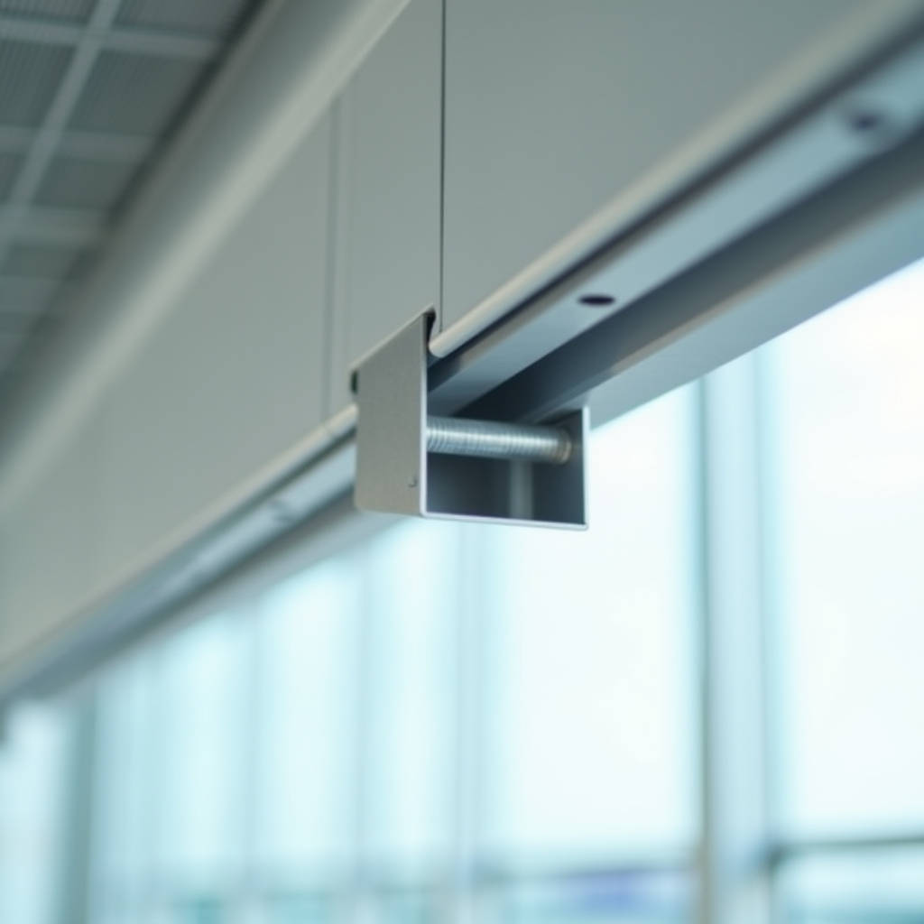
When a suspended aluminum baffle ceiling starts swaying under HVAC airflow or rattling during seismic events, the first component engineers inspect isn't the baffle itself — it's the Aluminum Baffle Bracket. This small, often overlooked connector determines whether a linear ceiling system stays plumb, resists lateral displacement, and maintains acoustic integrity over decades of service. In commercial and institutional projects — airports, transit hubs, university atriums, hospital corridors — the bracket assembly carries dead load, wind uplift, and vibration simultaneously. Getting the alloy grade, anodizing thickness, and mounting geometry right isn't optional. This article examines the bracket's structural role, material selection logic, installation tolerances, and the engineering decisions that separate a ceiling that performs from one that becomes a maintenance liability.
What Separates a Structural Bracket from a Cosmetic One
Not all aluminum brackets serving baffle ceilings are engineered for load-bearing. The distinction between a structural-grade Aluminum Baffle Bracket and a purely decorative clip comes down to three factors: alloy selection, cross-sectional design, and attachment methodology.
Structural brackets typically use 6063-T5 or 6061-T6 aluminum extrusions. 6063-T5 offers a yield strength of approximately 145 MPa and works well for interior applications where corrosion exposure is minimal. 6061-T6 pushes yield strength to roughly 240 MPa — a meaningful difference when the bracket must support baffle spans exceeding 3 meters or when the ceiling integrates lighting fixtures, sprinkler heads, and acoustic backing that add dead load. The T6 temper indicates solution heat treatment and artificial aging, producing a finer grain structure that resists crack propagation under cyclic loading.
Cosmetic clips, by contrast, often use 3003 or 5052 sheet aluminum bent into simple L-shapes or U-channels. These alloys work for lightweight interior baffles under 1.5 kg per linear meter but lack the fatigue resistance required for exterior soffits, high-bay atriums, or seismic zones. The problem surfaces when a bracket that looks adequate on a shop drawing fails after 18 months of thermal cycling — the aluminum work-hardens at the bend radius, micro-cracks form, and the baffle drops out of plane.
A practical field check: structural brackets almost always have a mill finish or clear anodized surface with visible extrusion die lines running longitudinally. Stamped and bent brackets show shear marks at cut edges and a duller surface from the forming process. If the bracket weighs less than 80 grams per unit for a 100 mm baffle, it's likely a cosmetic part, not a structural one.
Alloy Selection and Corrosion Chemistry
The choice between 6063 and 6061 isn't just about yield strength. It's about galvanic compatibility with the baffle itself, the fasteners, and the overhead suspension system.
Most solid aluminum baffles are extruded from 6063-T5. When the bracket shares the same alloy, the electrochemical potential difference is near zero — no galvanic cell forms even in the presence of condensation. This matters in natatoriums, commercial kitchens, and coastal airport terminals where relative humidity routinely exceeds 70%. If a contractor pairs a 6061-T6 bracket with a 6063 baffle, the potential difference is negligible (both are 6xxx series), but if they substitute a steel bracket with zinc plating, the galvanic corrosion accelerates dramatically. The zinc sacrificially corrodes, the steel rusts, and the bracket loses section thickness within 3-5 years.
Anodizing adds another layer of protection. A Class I clear anodized coating (AA-M12C22A31 per AAMA 611) provides 18 microns of aluminum oxide that electrically insulates the bracket surface. For exterior applications, Class II architectural anodizing at 25 microns is the minimum specified by most curtain wall consultants. The oxide layer is harder than the base aluminum — roughly 350 HV on the Vickers scale versus 75 HV for the substrate — which also improves scratch resistance during installation.
Powder coating on brackets introduces a risk: if the coating chips at fastener holes, the exposed aluminum becomes anodic relative to the intact coated area, concentrating corrosion at the mechanical connection. For this reason, many specifiers require brackets to be anodized rather than powder coated, or they mandate stainless steel shoulder washers that isolate the fastener from the bracket.
Load Path Analysis: Dead Load, Wind, and Seismic
An Aluminum Baffle Bracket doesn't just hold a baffle vertically — it must resist three distinct load vectors simultaneously.
Dead load is the simplest: the self-weight of the baffle plus any integrated services. A typical 100 mm × 50 mm extruded aluminum baffle with 1.6 mm wall thickness weighs approximately 2.1 kg/m. Over a 4-meter span, that's 8.4 kg per baffle, distributed across two or three brackets. If each bracket carries 4.2 kg, the tensile stress on the M6 stainless steel threaded rod connecting bracket to the overhead channel is under 2 MPa — well within safe limits.
Wind uplift changes the calculation entirely. In open-air soffits under canopies or at transit platform edges, negative wind pressure can exceed 1.5 kPa in wind zones per ASCE 7. A baffle with a 100 mm face width and 4-meter length presents 0.4 m² of projected area. At 1.5 kPa, the uplift force is 0.6 kN — roughly 60 kg trying to lift the baffle off its brackets. The bracket's grip mechanism must resist this without deformation. Spring-loaded wedge connectors and positive-lock cam systems outperform friction-fit designs here. A friction-fit bracket that relies solely on the extrusion's internal ribs can slip when the baffle vibrates under wind gusting, gradually loosening over months.
Seismic load introduces lateral displacement. Building codes such as the International Building Code (IBC) require suspended ceilings in Seismic Design Category D and above to accommodate interstory drift. For baffle ceilings, this means the bracket must allow the baffle to swing laterally without disengaging. A bracket with a 15 mm deep socket and a 3 mm engagement lip provides enough capture to handle ±25 mm of lateral movement. Brackets with shallower sockets — under 10 mm — risk disengagement during a seismic event, turning baffles into falling hazards.
Installation Tolerance Stacking and Field Adjustability
Shop drawings rarely match site conditions. Concrete slabs have camber, steel trusses deflect under load, and the main ceiling grid rarely sits perfectly level across a 500 m² floor plate. The bracket must absorb these deviations.
A well-designed Aluminum Baffle Bracket includes vertical adjustability of at least ±15 mm. This is typically achieved through a slotted connection where the M6 or M8 threaded rod passes through the bracket body. The slot allows the installer to fine-tune each baffle's elevation without shimming — critical when the baffle bottom edge is the visible reference plane and the human eye can detect a 3 mm deviation across a 10-meter sightline.
Horizontal adjustability matters equally. Baffle spacing (module) is specified to the millimeter — 75 mm, 100 mm, 150 mm centers — but the overhead carrier grid may be installed with ±5 mm tolerance. Brackets with an elongated top flange that slides along the carrier channel let the installer correct module alignment without drilling new holes. This feature alone can save 30-40% of installation labor on a project with 2,000 linear meters of baffles.
Rotational alignment is the third axis. Baffles must hang plumb; a 1-degree rotation is visible as a shadow line discrepancy. Brackets with a keyed profile that matches the baffle's internal geometry eliminate rotation. For rectangular baffles, a square socket with a tolerance of +0.3 mm over the baffle width ensures the baffle seats squarely without play. For curved or custom-profile baffles, the bracket socket must be machined to match the exact extrusion profile — a universal bracket won't work.
Coastal and High-Corrosion Environments
Projects within 5 km of saltwater coastlines demand bracket specifications that go beyond standard architectural anodizing. Salt spray testing per ASTM B117 provides the benchmark: a bracket that survives 1,500 hours of continuous salt fog without pitting or white rust is suitable for coastal use.
For these environments, 6061-T6 with Class II anodizing (25 microns) is the baseline. Some specifiers go further, requiring brackets machined from 5083 aluminum — a marine-grade alloy with 4.0-4.9% magnesium content that resists chloride-induced stress corrosion cracking. 5083 brackets cost roughly 2.5 times more than 6063 equivalents but are specified for offshore platform accommodation modules, desalination plant ceilings, and beachfront hotel soffits where replacement access is difficult.
Stainless steel fasteners are mandatory in these environments. A2 (304) grade is adequate for most coastal projects; A4 (316) grade is specified when the bracket is within 500 meters of breaking surf or in industrial zones with airborne sulfur compounds. The fastener must be physically isolated from the aluminum bracket with a nylon or EPDM washer to prevent galvanic coupling.
Futeng® has supplied custom 5083 baffle brackets for several Southeast Asian coastal resort projects, machining the socket geometry to match non-standard baffle profiles while maintaining the 25-micron anodized finish across all surfaces including internal threads.
Comparative Analysis: Bracket Types by Application
The following table summarizes bracket selection logic across common project types. The data reflects typical specifications encountered in commercial bidding documents across North America, the Middle East, and Asia-Pacific markets.
| Application | Recommended Alloy | Finish | Adjustability | Load Capacity (per bracket) | Typical Cost Index |
|---|---|---|---|---|---|
| Interior office ceiling, standard baffle | 6063-T5 | Clear anodized, Class I (18 µm) | ±10 mm vertical | 5 kg | 1.0 (baseline) |
| Airport terminal, high-bay atrium | 6061-T6 | Clear anodized, Class II (25 µm) | ±15 mm vertical, ±5 mm horizontal | 12 kg | 1.8 |
| Transit platform soffit (exterior) | 6061-T6 | PVDF coated (AAMA 2605) | ±15 mm vertical, ±5 mm horizontal, ±3° rotational | 15 kg (wind-rated) | 2.4 |
| Coastal resort, open-air canopy | 5083-H116 | Class II anodized (25 µm) + sealing | ±15 mm vertical, ±5 mm horizontal | 12 kg | 2.8 |
| Seismic zone (SDC D-F), hospital | 6061-T6 | Clear anodized, Class II (25 µm) | ±20 mm lateral slip, ±15 mm vertical | 10 kg (with seismic clip) | 2.2 |
| Industrial facility, chemical exposure | 5083-H116 | Epoxy-coated + anodized | ±10 mm vertical | 10 kg | 3.2 |
The cost index uses the interior office bracket as baseline 1.0. Actual pricing varies with order quantity, extrusion die complexity, and regional fabrication rates. The jump from 6063 to 6061 typically adds 40-60% to material cost; the jump to 5083 adds another 50-80%. For a 10,000 m² project with 15,000 brackets, the alloy decision alone can swing the bracket budget by $25,000-$45,000 — enough to warrant careful engineering review rather than defaulting to the cheapest option.
Acoustic Implications of Bracket Design
Baffle ceilings are often specified for acoustic control — breaking up sound reflections in large-volume spaces. The bracket influences acoustic performance in two ways: through structural coupling and through its own resonant behavior.
Structural coupling occurs when the bracket rigidly connects the baffle to the overhead slab. Vibrations in the slab — from footfall, mechanical equipment, or external traffic — transmit through the bracket into the baffle, which can then re-radiate the sound as structure-borne noise. A bracket with an EPDM or neoprene isolation gasket decouples this path. The gasket, typically 2-3 mm thick with a Shore A hardness of 50-60, reduces vibration transmission by 8-12 dB in the 125-500 Hz range where human speech intelligibility is most affected.
The bracket itself can resonate. A flat aluminum bracket with a free length over 80 mm has a natural frequency that may fall within the 60-200 Hz range — exactly where HVAC duct rumble and electrical transformer hum concentrate. If the bracket resonates, it acts as a secondary sound source. The fix is either a ribbed extrusion profile that increases stiffness without adding mass, or a constrained-layer damping pad bonded to the bracket body. The latter is more common in performing arts venues and recording studios where background noise criteria are stringent (NC-15 or lower).
For standard commercial projects, the acoustic impact of bracket choice is secondary to the baffle's own NRC rating. But in acoustically sensitive spaces — courtrooms, concert halls, broadcast studios — the bracket specification should be reviewed by the acoustical consultant alongside the baffle selection.
Quality Verification: What to Check Before Shipment
Procurement managers and project engineers inspecting Aluminum Baffle Bracket shipments should verify the following parameters before accepting delivery. These checks apply whether sourcing from domestic fabricators or international suppliers.
Dimensional verification: Measure socket width, depth, and wall thickness at five random samples per 500-unit lot. Socket width tolerance should be +0.3/-0.0 mm relative to the baffle's outer dimension. A socket that's too tight (negative tolerance) will gall the baffle's anodized surface during installation; too loose (over +0.5 mm) and the baffle will rattle under airflow.
Anodizing thickness: Use an eddy-current gauge per ISO 2360. For Class I, minimum 18 µm on all accessible surfaces. For Class II, minimum 25 µm. Reject lots where any measurement falls below 80% of the specified minimum.
Hardness: A Webster hardness tester applied to the bracket body should read 8-12 for 6063-T5 and 12-16 for 6061-T6. Lower readings indicate under-tempered material that may have been extruded at excessive temperature or inadequately aged.
Thread engagement: For brackets with tapped holes for grub screws or set screws, verify that an M6 or M8 stainless steel bolt can be threaded to full depth without binding. Cross-threading in the factory suggests worn tapping tools or inadequate chip clearance during machining.
Fit test: Slide a sample bracket onto a sample baffle section. It should engage smoothly with hand pressure and lock positively without tools. If the bracket requires hammering to seat, the socket is undersized. If it falls off under its own weight, the grip mechanism is defective.
Supply Chain Considerations for International Projects
For projects in the Middle East, Southeast Asia, and North America, bracket sourcing intersects with several logistical realities.
Extrusion die lead time is the biggest schedule driver. A custom bracket profile requires a new die, which takes 3-4 weeks to manufacture and another 1-2 weeks for trial extrusion and dimensional verification. If the bracket design isn't finalized until after the main baffle order is placed, the bracket delivery can delay the entire ceiling package by 6-8 weeks. Experienced contractors order brackets concurrently with baffles, not sequentially.
Minimum order quantities (MOQs) for custom extrusions typically range from 300-500 kg per die. For a lightweight bracket weighing 80 grams, that's 3,750-6,250 units. Projects with fewer than 1,000 linear meters of baffles may fall below this threshold, in which case a standard bracket profile with machined adapters may be more economical than a fully custom extrusion.
Sea freight from Asian fabrication hubs to North American West Coast ports takes 18-22 days; to European ports, 28-35 days. Air freight cuts this to 3-5 days but costs roughly 6-8 times more. For a 500 kg bracket shipment, the air freight premium can exceed $4,000 — tolerable if the brackets are on the critical path, but wasteful if planned properly.
Tariff classification matters. Aluminum brackets fall under HS Code 7610.90 (aluminum structures and parts). Import duties vary by country of origin and destination; the US Section 301 tariffs on Chinese aluminum extrusions can add 25% to the landed cost. Some projects mitigate this by sourcing brackets from Vietnam or Malaysia, though the extrusion industry in those countries has less capacity for complex architectural profiles.
When to Specify Custom Brackets vs. Standard Systems
Standard baffle ceiling systems from manufacturers like Armstrong or Knauf include proprietary bracket designs that work well for their specific baffle profiles. These brackets are tested, code-compliant, and readily available. For most commercial interior projects, they're the right choice.
Custom brackets become necessary when:
- The baffle profile is non-standard — curved, tapered, perforated with non-rectangular geometry, or exceeding 300 mm in face height
- The project requires a specific alloy or finish not offered in the standard system (e.g., 5083 marine-grade, PVDF color-matched to the facade)
- Seismic or wind loads exceed the standard bracket's rated capacity
- The overhead structure is irregular — arched steel trusses, curved concrete shells, or timber beams where standard carrier channels can't be mounted
- The architect requires concealed fastening with zero visible hardware from any viewing angle
The engineering cost for a custom bracket — including die design, FEA analysis, and physical load testing — typically ranges from $3,000 to $8,000. Amortized over 5,000+ units, the per-unit premium is modest. On smaller projects, the engineering cost may exceed the bracket material cost, making a standard system with field modifications more practical.
The bracket is the silent partner in every baffle ceiling installation. It doesn't appear in architectural renderings. It's rarely discussed in design meetings. But when it's underspecified, the consequences are visible — and expensive. A baffle ceiling that sags, rattles, corrodes, or disengages during a seismic event represents a failure that starts at the connection point. Specifying the right alloy, finish, adjustability range, and load capacity for the Aluminum Baffle Bracket is an engineering decision that deserves the same rigor applied to the baffles themselves. For project teams navigating this specification, the key is to define the bracket's performance requirements — not just its geometry — in the tender documents, and to verify compliance through physical inspection rather than relying solely on mill certificates.