Aluminum Parapet Cap Wind Load Design and Thermal Movement Engineering for Commercial Buildings
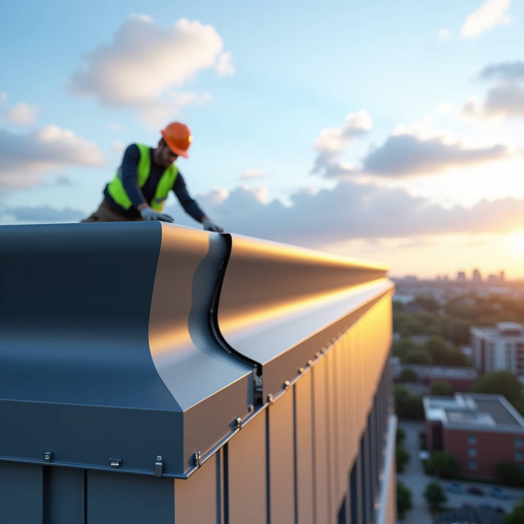
An Aluminum Parapet Cap does more than finish the top of a wall. When a building rises above 20 stories, that narrow strip of metal becomes the first line of defense against wind-driven rain, freeze-thaw cycling, and structural movement. Architects specify it as a visual crown. Structural engineers count on it to keep water out of the wall assembly. And contractors know that if the cap fails, everything below it is at risk. Getting the profile right, the gauge right, and the anchorage right separates a coping system that lasts 40 years from one that leaks in the first heavy storm. This article walks through what matters most when selecting and installing aluminum parapet caps on mid-rise and high-rise commercial projects, with a focus on wind performance, thermal movement accommodation, and the fabrication details that make the difference between a dry building and a call-back nightmare.
What Separates a Structural Aluminum Parapet Cap from a Decorative Trim
Not every piece of bent aluminum sitting on a parapet wall performs the same job. A true Aluminum Parapet Cap functions as part of the building envelope. It carries wind loads, directs water away from the wall, and accommodates thermal expansion across joints that can open and close a quarter-inch between summer and winter. Decorative trims sold through residential channels typically come in 0.040-inch or 0.050-inch thicknesses, with simple hemmed edges and no positive anchorage. They rely on friction or construction adhesive to stay in place. That approach fails on a commercial parapet where wind uplift pressures routinely exceed 30 psf at corners and roof edges.
The structural coping systems used in commercial construction start at 0.078-inch (2.0mm) aluminum and go up to 0.125-inch (3.0mm) for wide parapets or high-wind zones. The difference is not just durability. Thicker material allows the cap to span between anchor clips without sagging, resist fastener pull-through under suction loads, and maintain its profile over decades of thermal cycling. A 0.040-inch cap will oil-can visibly on a hot afternoon. A 2.5mm cap will not.
Material Grade and Temper Matter
Aluminum parapet caps in commercial applications are fabricated from 3003-H14 or 5052-H32 alloy sheet. 3003-H14 offers good formability for standard profiles and holds a PVDF finish well. 5052-H32 provides higher tensile strength and better corrosion resistance, making it the preferred choice for coastal installations or projects within 3 miles of saltwater. The temper designation matters because it determines how the metal behaves during brake forming. Over-bending H32 material without proper radius compensation can create micro-cracking at the bend line, which becomes a corrosion initiation point over time.
Fabricators who understand these distinctions will ask about project location before quoting. A 3003-H14 cap with Kynar 500 PVDF performs well in Chicago or Dallas. The same cap in Miami Beach or Galveston needs 5052-H32 with a thicker coating system to meet AAMA 2605 requirements for coastal exposure.
Wind Load Design and the ANSI/SPRI/FM 4435 ES-1 Standard
Parapet coping failures during wind events follow a predictable pattern. The leeward corner of the building experiences the highest negative pressure. The coping lifts, fasteners pull through or clips deform, and once a section breaks free, the entire run can peel off. This is not a hypothetical scenario. Post-hurricane damage assessments consistently identify parapet coping as one of the most frequently compromised building envelope components.
The industry responded with ANSI/SPRI/FM 4435 ES-1, which establishes test procedures for evaluating the wind resistance of edge systems including parapet coping. ES-1 testing subjects the coping assembly to three load conditions: outward (suction), inward (pressure), and rotational. The test protocol requires the assembly to maintain structural integrity and water penetration resistance at design wind loads with a safety factor applied.
Specifying an ES-1 tested coping system shifts liability from the design team to the manufacturer. The test report provides documented capacity that the engineer of record can compare against project-specific wind loads calculated per ASCE 7. For a 15-story building in Exposure Category C, corner zone pressures can reach 45 to 60 psf. A coping system rated for 90 psf per ES-1 testing provides the required safety margin. Systems without test data leave the specifier guessing.
Clip Spacing and Anchorage Design
Wind load capacity is not just about the cap profile. Clip spacing, fastener type, and substrate condition all factor into the assembly performance. Most ES-1 tested systems specify clip spacing at 12 inches on center for standard conditions and 8 inches on center for corner zones. The clips themselves are typically 0.063-inch or 0.080-inch stainless steel, pre-punched for positive attachment to the parapet substrate.
On concrete parapets, wedge anchors or screw anchors with a minimum embedment of 1.5 inches are standard. On steel stud parapets, self-drilling screws into minimum 16-gauge backing are required. The clip must engage the coping profile with enough mechanical interlock to resist the rotational moment that wind creates. A snap-on cap that relies on spring tension alone will not meet ES-1 requirements. The best systems use a positive locking mechanism that requires deliberate tool pressure to release.
Thermal Movement: Why Joints Leak and How to Stop It
Aluminum expands and contracts at roughly 0.0000129 inches per inch per degree Fahrenheit. For a 20-foot run of coping, a 100°F temperature swing from a cold winter night to a hot summer afternoon produces approximately 0.31 inches of movement. That movement has to go somewhere. If the coping is installed with tight butt joints, the metal will buckle. If the splice plates are undersized, they will pull apart and create a direct path for water into the wall.
The standard detail for accommodating thermal movement in an Aluminum Parapet Cap system uses a concealed splice plate with a factory-applied sealant gutter. The splice plate slides inside the adjacent coping sections, allowing each piece to move independently while maintaining a continuous water barrier beneath the joint. The visible gap between coping sections should be calculated based on the expected temperature range at installation, not simply set at a uniform 1/8 inch. A cap installed at 40°F in February will close that gap significantly when the roof surface hits 140°F in July.
Calculating Joint Width for Your Climate Zone
The formula for minimum joint width is straightforward: Joint Width = (Coefficient of Thermal Expansion × Length × Temperature Change) + 1/16-inch minimum clearance. For a 12-foot coping section in Minneapolis, where the annual temperature swing can exceed 130°F, the calculation yields roughly 0.24 inches of movement. Adding the minimum clearance gives a required joint of 5/16 inch. The same section in San Diego, with a 50°F swing, needs only about 1/8 inch. Getting this wrong means coping sections that bind against each other, deforming clips and opening gaps at the splice plates.
Experienced installers will also stagger the splice plate locations relative to the anchor clips. Placing a splice directly over a clip creates a rigid point that concentrates movement at adjacent joints. Offsetting splices by at least 6 inches from clips allows the entire assembly to float more evenly.
Coating Systems and Long-Term Weathering Performance
The aluminum substrate provides the structural function, but the coating system determines how the cap looks after 10, 15, and 20 years of exposure. Two coating standards dominate commercial specifications: AAMA 2604 and AAMA 2605. The difference comes down to resin chemistry and film thickness.
AAMA 2604 coatings use a 70% PVDF resin system applied at a minimum dry film thickness of 0.8 mil. They provide good color retention and chalk resistance for 10 to 15 years in most environments. AAMA 2605 coatings use a 70% PVDF resin system with proprietary ceramic pigments, applied at a minimum 1.2 mil dry film thickness. The additional film thickness and higher-grade pigments extend the performance window to 20 to 30 years with minimal color fade and chalking. For a parapet cap that sits at the most visually prominent edge of the building, the incremental cost of AAMA 2605 over 2604 is typically less than 15% of the total installed coping cost and pays back in reduced maintenance and replacement liability.
| Coating Standard | Resin System | Min. Dry Film Thickness | Color Retention (10 Yr) | Chalk Resistance | Typical Warranty | Best Application |
|---|---|---|---|---|---|---|
| AAMA 2603 | Polyester | 0.8 mil | Delta E < 5 | Moderate | 5-10 years | Interior, sheltered |
| AAMA 2604 | 70% PVDF | 0.8 mil | Delta E < 3 | Good | 10-15 years | Mid-rise commercial |
| AAMA 2605 | 70% PVDF + Ceramic | 1.2 mil | Delta E < 2 | Excellent | 20-30 years | High-rise, coastal |
| FEVE (Fluoropolymer) | Lumiflon-based | 1.5 mil | Delta E < 2 | Excellent | 20-30 years | High-gloss, complex shapes |
One detail often overlooked is the coating on the underside of the cap. Water that condenses on the underside of the coping can drip back onto the parapet substrate if the coating is incomplete. A proper Aluminum Parapet Cap should have a wash coat or full finish coat on the underside, particularly at the drip edge where water will collect and release. Skipping this step saves a few dollars per linear foot and creates a corrosion cell that will eventually telegraph through to the visible surface.
Profile Geometry and Water Management
The cross-section of a parapet cap looks simple from the ground, but the geometry determines how water behaves. The three critical elements are the top slope, the drip edge, and the end dam at terminations.
The top surface must slope a minimum of 1/4 inch per foot toward the roof side of the parapet. This directs water away from the exterior facade, where streaking and staining would be visible. On wide parapets exceeding 24 inches, a single slope may not be sufficient. A cricket or double-slope profile that drains to both sides prevents ponding in the center of the cap. Standing water on a flat coping accelerates coating degradation and creates a freeze-thaw hazard in cold climates.
The drip edge at each side of the cap should extend a minimum of 3/4 inch beyond the face of the parapet wall and incorporate a continuous drip kerf or hem. Without this break, surface tension causes water to cling to the underside of the cap and run back against the wall. The drip edge creates a clean detachment point where water falls free. On the roof side, the drip should be positioned to direct water onto the roofing membrane or into the gutter, not behind the membrane flashing.
End Dams and Termination Details
Where the parapet cap terminates at a wall, a higher roof section, or an expansion joint, an end dam must close off the profile. Water that enters the open end of a coping will travel laterally inside the cap and exit at the nearest joint or fastener penetration. End dams are typically fabricated from the same aluminum material as the cap, welded or sealed in place, and integrated with the wall flashing or counterflashing at the termination. A field-fabricated end dam made from scrap material and sealed with caulk will not last. Factory-fabricated end dams with continuous welds and shop-applied coating are the only reliable approach.
Fabrication Tolerances and Quality Control
Aluminum parapet caps are long, narrow components that are sensitive to fabrication tolerances. A cap that is 1/8 inch out of square over a 10-foot length will telegraph that error across every joint in the run. By the tenth section, the cumulative error can exceed an inch, making it impossible to maintain consistent joint widths and clip engagement.
Quality fabricators work to a tolerance of ±1/16 inch on profile dimensions and ±1/32 inch on bend angles. They use CNC press brakes with back-gauge systems that position the sheet accurately for each bend. The bend radius should be a minimum of 1.5 times the material thickness for 3003-H14 and 2 times the material thickness for 5052-H32 to prevent stress cracking. Sharper bends are possible but require the fabricator to orient the bend line perpendicular to the grain direction of the sheet.
Futeng® is one supplier that has built its aluminum coping fabrication around these tolerance standards, producing caps in 2.0mm, 2.5mm, and 3.0mm thicknesses with AAMA 2605 coating systems for projects across Southeast Asia, the Middle East, and North America. The key is not just the equipment but the inspection protocol: every coping section should be checked against a shop drawing before it leaves the factory floor.
Installation Sequencing and Trade Coordination
The parapet cap sits at the intersection of multiple trades. The roofing contractor installs the membrane and base flashing. The masonry or framing contractor builds the parapet wall. The metal panel contractor or sheet metal trade installs the coping. If the sequencing is wrong, the cap gets installed before the roofing is complete, and the roofer damages the coping or leaves gaps in the flashing. If the parapet substrate is out of tolerance, the coping installer has to shim and adjust, which compromises the clip engagement and wind rating.
The correct sequence places coping installation after the roofing membrane and base flashing are complete and inspected. The parapet substrate should be checked for flatness and plumb before clips are laid out. A tolerance of ±1/4 inch in 10 feet is reasonable for the substrate. Anything beyond that requires leveling with shims or a sloped fill at the top of the parapet. The coping installer should also verify that the roofing contractor has installed a continuous wood nailer or metal blocking at the parapet top to receive the anchor clips. Anchoring clips directly into hollow CMU without a continuous nailer is a common shortcut that reduces pull-out capacity by 40% or more compared to a properly blocked substrate.
Field Cutting and Touch-Up
Field cutting of coping sections is sometimes unavoidable at corners, penetrations, and terminations. The cut edge exposes bare aluminum that must be protected. A two-part epoxy touch-up coating applied to the cut edge within 24 hours of cutting is the minimum acceptable practice. For AAMA 2605 finishes, the touch-up coating should be from the same manufacturer and matched to the original color. Clear coatings on cut edges do not provide adequate corrosion protection. The touch-up should extend at least 1/2 inch beyond the cut onto the factory-finished surface to seal the interface.
Cost Drivers and Value Engineering Without Compromise
The installed cost of an Aluminum Parapet Cap system ranges from $25 to $65 per linear foot, depending on material thickness, coating specification, profile complexity, and project location. The material itself typically represents 40% to 55% of the installed cost. Labor, clips, fasteners, and sealants make up the balance.
When value engineering pressure hits, the first target is often material thickness. Reducing from 0.080-inch (2.0mm) to 0.063-inch (1.6mm) saves about 20% on material cost but reduces spanning capacity and wind resistance. A better approach is to simplify the profile geometry while maintaining the specified thickness. A single-slope cap with a simple drip edge costs less to fabricate than a multi-rib profile with integrated gutters, and the performance difference is often negligible for standard parapet conditions.
Another cost-saving measure that does not compromise performance is optimizing section lengths. Standard coping sections come in 10-foot or 12-foot lengths. On a building with 200 linear feet of parapet, using 12-foot sections instead of 10-foot sections reduces the number of joints by 17%, which means fewer splice plates, fewer clips at joints, and less labor for joint sealing. The material cost difference is negligible, but the labor savings can be significant on a large project.
Specifying an ES-1 tested coping system with a documented wind rating is not a cost premium. It is an insurance policy against the most common parapet failure mode. The incremental cost of tested versus untested coping is typically less than 8% of the total coping package.
Coastal and Severe Environment Considerations
Buildings within 3 miles of saltwater face a different set of requirements for aluminum coping. Salt spray deposits on the cap surface, and if the coating has any porosity or thin spots, the chloride ions will initiate pitting corrosion. The standard response is to specify 5052-H32 alloy with a AAMA 2605 coating applied at the upper end of the film thickness range (1.4 to 1.5 mils).
An additional measure that is often overlooked is the use of stainless steel fasteners and clips throughout the assembly. Zinc-plated steel fasteners in contact with aluminum in a marine environment create a galvanic couple that accelerates corrosion of the aluminum. Type 304 or 316 stainless steel fasteners eliminate this risk. The cost difference is about $0.50 per clip assembly, which is negligible compared to the cost of replacing corroded coping on a 20-story building.
For projects in the Middle East, where sand abrasion and UV exposure are the dominant environmental factors, the coating specification should emphasize chalk resistance and color stability. AAMA 2605 coatings with ceramic pigments are the baseline. Some manufacturers offer FEVE-based fluoropolymer coatings that provide even higher gloss retention and abrasion resistance, though at a 15% to 20% premium over standard PVDF. The decision depends on whether the parapet cap is visible from street level or only from adjacent rooftops.
Specification Checklist for the Project Manual
Writing a specification that gets the right Aluminum Parapet Cap on the building requires more than referencing a manufacturer's product name. The spec should address the following points explicitly:
- Material: 3003-H14 or 5052-H32 aluminum sheet, 2.0mm (0.078-inch) minimum thickness for standard conditions, 2.5mm or 3.0mm for wide parapets or high-wind zones
- Coating: AAMA 2605 minimum, with AAMA 2604 acceptable only for interior or sheltered applications
- Wind performance: ANSI/SPRI/FM 4435 ES-1 tested and rated for project-specific design wind loads per ASCE 7
- Clip system: Stainless steel, minimum 0.063-inch thickness, with positive mechanical engagement to coping profile
- Fasteners: Stainless steel Type 304 minimum, Type 316 for coastal environments
- Thermal movement: Concealed splice plates with integral sealant gutter, joint width calculated per project climate data
- Fabrication tolerances: ±1/16 inch on profile, ±1/32 inch on bend angles
- Substrate: Continuous wood nailer or metal blocking at parapet top, verified flat within ±1/4 inch per 10 feet
- Touch-up: Two-part epoxy coating matched to factory finish, applied to all field-cut edges within 24 hours
Including these criteria in Division 07 62 00 (Sheet Metal Flashing and Trim) or a dedicated coping section gives the contractor clear performance requirements and allows the specifier to evaluate substitutions on a technical basis rather than a price comparison alone.
The parapet cap is a small fraction of the total building envelope cost, typically less than 2% on a mid-rise commercial project. But the damage from a failed coping system can run into six figures when water infiltration reaches interior finishes, insulation, and structural framing. The engineering time spent on coping specification pays back many times over across the service life of the building. Get the alloy right, get the coating right, get the anchorage right, and the cap will do its job quietly for decades.