Aluminum Sill Flashing Engineering for Commercial Building Envelope Water Management
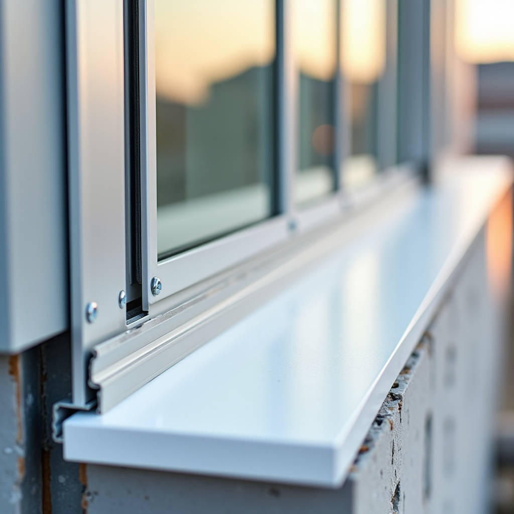
When water finds its way behind a curtain wall system at the sill level, the damage unfolds silently over months and years. Aluminum Sill Flashing is the engineered metal barrier installed at the base of window and door openings within commercial building envelopes, designed to intercept moisture that penetrates the glazing plane and redirect it outward to the drainage plane. For general contractors and facade engineers managing multistory projects, the specification of sill flashing involves decisions about material gauge, alloy selection, end dam geometry, and compatibility with the surrounding air and water barrier system. A poorly specified sill flashing detail can compromise an entire floor line, leading to mold propagation, insulation degradation, and structural rot in steel or wood backup framing. The stakes are high because the sill is the most vulnerable horizontal transition in any drained wall assembly. This article examines the technical factors that determine whether an aluminum sill flashing system performs reliably across a 30-year building lifecycle, focusing on alloy chemistry, fabrication tolerances, and the integration challenges that arise on large-scale commercial facades.
Why the Sill Is the Weakest Link in a Drained Facade
Water moves through a building envelope under the combined influence of gravity, capillary action, air pressure differentials, and kinetic energy from wind-driven rain. The sill condition at window and door openings concentrates all four forces at a single horizontal plane. Rainwater running down the glass surface hits the sill and pools. Wind pressure pushes that water against the gap between the frame and the rough opening. Capillary suction draws moisture into microscopic cracks. Unlike head and jamb flashings, which primarily shed water downward, sill flashings must collect water, contain it laterally, and discharge it through weep paths without allowing any inward migration.
The physics gets more demanding on taller buildings. At 100 feet above grade, wind pressures can exceed 30 psf in storm conditions, and the stack effect within the cavity creates negative pressure that actively pulls water inward. Aluminum Sill Flashing in these conditions must function as a pressure-equalized drainage element, not merely a gravity-fed drip edge. This means the flashing profile needs a positive slope to the exterior, a back dam tall enough to resist the pressure head, and end dams that prevent lateral spillover into the jamb cavities. Field observations from forensic investigations consistently show that sill flashing failures account for a disproportionate share of water intrusion claims in commercial curtain wall and storefront systems.
Alloy Selection Matters More Than Most Specifiers Realize
Not all aluminum is the same. The aluminum flashing products found at consumer retail outlets are typically fabricated from 1100 or 3003 alloys in the H14 temper, with thicknesses around 0.019 inches (0.48 mm). These materials are adequate for residential window flashing in low-rise construction but fall short for commercial applications. For curtain wall and storefront systems on buildings exceeding three stories, the sill flashing should be fabricated from 5052-H32 or 6061-T6 aluminum alloy at a minimum thickness of 0.040 inches (1.0 mm), and often 0.050 inches (1.27 mm) for high-wind zones.
The rationale comes down to three material properties: yield strength, corrosion resistance in alkaline environments, and formability for end dam fabrication. 5052-H32 offers a yield strength of approximately 28 ksi (193 MPa), roughly double that of 1100-H14. This matters because the back dam of a sill flashing acts as a cantilever beam resisting the pressure of pooled water and wind. A 0.040-inch 5052-H32 back dam can withstand substantially higher loads without permanent deformation than a 0.019-inch 1100-H14 equivalent. The corrosion issue is equally important: aluminum in contact with wet mortar, concrete, or certain sealant chemistries can experience galvanic corrosion or alkaline attack. 5052 alloy, with its 2.5% magnesium content, provides better resistance to these conditions than commercially pure 1100 aluminum.
For projects requiring compatibility with solid aluminum cladding panels in the 2.0 mm to 3.0 mm thickness range, the sill flashing alloy should be matched to the panel alloy to avoid galvanic couples. When 6061-T6 panels are specified, the flashing should also be 6061-T6. When 5052 panels are used, the flashing should follow suit. This attention to alloy continuity is a detail that experienced facade manufacturers like Futeng® address during the shop drawing phase, ensuring that the entire aluminum envelope performs as a unified system rather than a collection of incompatible components.
End Dams, Back Dams, and the Geometry of Water Containment
The Building Science Corporation's technical bulletin on pan flashing for exterior wall openings identifies end dams and back dams as the two most critical geometric features of any sill flashing system. A back dam is the upturned leg at the interior edge of the sill pan that prevents water from spilling backward into the building interior. An end dam is the upturned leg at each side of the pan that prevents water from running laterally into the jamb cavities. Both features must be tall enough to resist the expected hydrostatic pressure head under design wind conditions.
For commercial buildings, the back dam height should be a minimum of 1 inch (25 mm), and end dams should match that height with a continuous weld or folded corner that eliminates any gap at the junction. The most common failure observed in the field is a back dam that gets bent or crushed during window installation, creating a breach that allows direct water entry. To prevent this, the back dam should be reinforced with a hemmed edge or a secondary stiffener angle, and the installation sequence should protect the flashing until the window unit is set and fastened.
The slope of the sill pan is another geometric variable that is often overlooked. A flat sill pan relies entirely on wind pressure or evaporation to clear water. A pan with a 5-degree slope to the exterior uses gravity to drain water toward the weep slots. Achieving this slope in the field requires either a tapered substrate, a sloped shim system, or a factory-fabricated pan with an integral slope. The factory-fabricated approach is more reliable because it removes the slope variable from the installer's responsibility. For projects using solid aluminum cladding panels, the sill flashing slope should be coordinated with the panel joint layout to ensure that drainage paths align with open joints or weep holes in the panel system.
Integration With Air and Water Barrier Systems
The most technically challenging aspect of Aluminum Sill Flashing specification is not the flashing itself but the transition between the flashing and the adjacent air and water barrier membranes. The sill flashing sits at the intersection of the rough opening, the window frame, the wall cavity, and the exterior cladding. Each of these planes has its own waterproofing layer, and the flashing must tie into all of them without creating a dam that traps water behind the barrier.
The industry standard approach follows the "shingle lap" principle: each layer of the building envelope must lap over the layer below it so that water always drains outward and downward. At the sill, this means the air barrier membrane on the wall should lap onto the vertical leg of the sill flashing, and the flashing itself should extend outboard of the cladding drainage plane. The window unit then sits on setting blocks within the pan, and the interior air seal connects the window frame to the back dam or the interior wall membrane.
A common integration error is to seal the bottom of the sill flashing to the air barrier in a way that prevents drainage. If sealant is applied continuously along the bottom edge of the flashing where it meets the rough opening, any water that enters the pan has no path to escape. The correct detail leaves the bottom edge of the flashing open or provides discrete weep slots at the front edge, allowing water to drain freely while the back dam and end dams contain it laterally.
For projects using self-adhering flashing membranes with aluminum facers, such as those meeting AAMA 711-13 standards, the compatibility between the membrane adhesive and the aluminum sill flashing substrate must be verified. Some adhesives contain plasticizers that can migrate and attack certain aluminum alloys over time. A peel adhesion test conducted at the project's expected temperature extremes can identify compatibility issues before installation begins.
Fabrication Tolerances and Quality Control
Aluminum sill flashing for commercial projects is typically fabricated on a press brake from flat sheet stock. The precision of the bend angles, the consistency of the flange dimensions, and the quality of welded corners directly affect field performance. A back dam that is bent to 88 degrees instead of 90 degrees will not sit flush against the rough opening, creating a gap that compromises the air seal. An end dam that is 1/16 inch shorter than specified may not provide adequate water containment under heavy rain conditions.
The following table summarizes the recommended fabrication tolerances for commercial-grade aluminum sill flashing, based on industry standards and field experience:
| Dimension / Feature | Recommended Tolerance | Measurement Method | Impact of Non-Compliance |
|---|---|---|---|
| Back dam height | ± 1/16" (1.6 mm) | Calibrated height gauge | Reduced water containment capacity |
| End dam height | ± 1/16" (1.6 mm) | Calibrated height gauge | Lateral water leakage into jamb |
| Bend angle (all flanges) | ± 1 degree | Digital protractor | Poor fit against substrate; air seal gaps |
| Overall length | ± 1/8" (3.2 mm) | Steel tape measure | Gaps at ends requiring field shimming |
| Overall width | ± 1/8" (3.2 mm) | Steel tape measure | Interference with window frame or cladding |
| Weld seam integrity (end dam corners) | Continuous, no pinholes | Visual inspection + dye penetrant test | Water leakage through corner joint |
| Surface flatness (pan bottom) | ± 0.030" per 12" (0.76 mm per 305 mm) | Straightedge + feeler gauge | Water ponding; uneven support for window |
For large-scale projects, a first-article inspection should be conducted on a sample of fabricated sill flashings before production quantities are manufactured. This inspection should verify all critical dimensions against the approved shop drawings and confirm that the alloy and temper are as specified. A mill test report from the aluminum supplier provides traceability back to the original coil or sheet, which is important for projects requiring LEED or BREEAM material documentation.
Corrosion Protection and Finish Compatibility
Bare aluminum sill flashing will develop a natural oxide layer that provides some corrosion protection in mild environments, but this is insufficient for most commercial building locations. The flashing is exposed to condensation, cleaning chemicals, and potentially corrosive urban or marine atmospheres. A protective finish is essential, and the finish choice must be compatible with the adjacent cladding materials and sealants.
For aluminum sill flashing that is visible or semi-visible at the building exterior, a PVDF (polyvinylidene fluoride) coating system meeting AAMA 2605 standards provides the highest level of durability. This is the same coating specification used for premium solid aluminum cladding panels, with a typical dry film thickness of 30-35 microns in a three-coat system. The PVDF coating offers excellent resistance to UV degradation, chalking, and color fading over a 20-30 year service life. For flashing that is entirely concealed within the wall cavity, a less expensive polyester powder coating meeting AAMA 2603 may be adequate, provided the coating is applied to all surfaces including cut edges.
A critical but often overlooked detail is the treatment of field-cut edges. When sill flashing is cut to length on site, the cut edge exposes bare aluminum that lacks the factory-applied coating. This edge becomes a corrosion initiation point, particularly in coastal environments where salt spray accelerates pitting. The specification should require that all field-cut edges be treated with a touch-up coating or a chromate conversion coating within 24 hours of cutting. The touch-up material must be chemically compatible with the factory coating to avoid adhesion failures at the repair interface.
Thermal Movement and Attachment Methods
Aluminum has a coefficient of thermal expansion of approximately 23.6 × 10⁻⁶ m/m/°C (13.1 × 10⁻⁶ in/in/°F). For a 10-foot (3.05 m) length of sill flashing subjected to a 100°F (55°C) temperature swing over a year, the total length change is approximately 0.16 inches (4.0 mm). This movement must be accommodated in the attachment design to prevent buckling, fastener pullout, or sealant shear failure.
The standard approach is to use slotted fastener holes that allow the flashing to slide relative to the substrate. A fixed point is established at the center of the flashing length, with slots oriented outward from the center in both directions. The slot length should be calculated based on the expected temperature range and the distance from the fixed point, with a minimum slot length of 3/8 inch (10 mm) for typical commercial applications. Fasteners should be stainless steel (Type 304 or 316) to avoid galvanic corrosion with the aluminum flashing, and they should be fitted with nylon or EPDM washers to reduce friction and allow movement.
For sill flashing integrated with solid aluminum cladding panels, the thermal movement characteristics of both components must be coordinated. If the panel system uses a cassette or rainscreen attachment with its own movement joints, the sill flashing should not bridge those joints rigidly. Instead, the flashing should be segmented at the panel movement joints, with each segment independently attached and the joint between segments detailed with a slip joint or a flexible sealant bridge.
Weep Systems and Drainage Capacity
The weep system is the exit path for water that has been collected by the sill flashing. Without adequate weep capacity, water will accumulate in the pan until it overtops the back dam or finds another path into the building. The weep design must balance two competing requirements: the openings must be large enough to drain water faster than it enters the pan, but small enough to resist insect entry, wind-driven rain penetration, and excessive air leakage.
The minimum weep area recommended by the AAMA is 1 square inch of net free area per 20 square feet of wall area, but this is a general guideline that does not account for local rainfall intensity. For commercial buildings in regions with design rainfall rates exceeding 3 inches per hour, the weep capacity should be calculated using the rational method: Q = CIA, where Q is the flow rate, C is the runoff coefficient (typically 0.95 for glass), I is the design rainfall intensity, and A is the tributary area of glazing draining to the sill. The weep openings must be sized to handle Q with a factor of safety of at least 2.0 to account for partial blockage by debris over time.
Weep slots in aluminum sill flashing are typically formed as oblong holes, 1/4 inch by 1 inch (6 mm by 25 mm), spaced at 12 to 16 inches (305 to 406 mm) on center. Alternatively, continuous weep slots can be formed by leaving a gap between the sill flashing and the exterior cladding, with a perforated closure or insect screen to prevent pest entry. The continuous weep approach provides more uniform drainage and is less susceptible to blockage than discrete slots, but it requires careful detailing to maintain the visual appearance of the facade.
Coordination With Solid Aluminum Cladding Panel Systems
When Aluminum Sill Flashing is specified as part of a facade that includes solid aluminum cladding panels in the 2.0 mm to 3.0 mm thickness range, the interface between the flashing and the panels demands particular attention. The sill flashing typically extends from the window frame outward to the face of the cladding, creating a horizontal break in the panel layout. This break must be detailed to maintain the drainage plane continuity while accommodating the different thermal movement rates of the flashing and the panels.
The preferred detail is to have the sill flashing project slightly beyond the face of the cladding panels, forming a drip edge that prevents water from running down the panel face and entering the joint below. The projection should be a minimum of 3/8 inch (10 mm) and should include a downturned drip leg with a sharp break to encourage water droplet formation and release. The gap between the back of the drip leg and the face of the panel should be a minimum of 1/4 inch (6 mm) to allow for thermal movement and to prevent capillary bridging.
For projects where the sill flashing must match the color and finish of the adjacent cladding panels, the PVDF coating on the flashing should be applied by the same coating applicator using the same paint batch as the panels. Even with the same paint code, variations between batches can produce visible color differences under certain lighting conditions. Specifying a single-source coating application for all visible aluminum components eliminates this risk. Manufacturers with integrated fabrication and coating capabilities can provide this level of color consistency across panels, flashings, and trim components.
Installation Sequencing and Quality Assurance
The best-designed sill flashing will fail if it is installed out of sequence or without adequate quality control. The correct installation sequence begins after the rough opening is framed and the air barrier is installed on the wall but before the window unit is placed. The sill flashing is set first, shimmed to achieve the specified slope, and fastened to the substrate. The air barrier membrane is then lapped over the back dam and sealed. The window unit is set on setting blocks within the pan, and the jamb and head flashings are installed in sequence, each lapping over the one below.
A water test should be conducted after the flashing is installed but before the window unit is set. This test involves spraying water on the wall above the opening and verifying that water drains through the sill flashing weeps without entering the building interior. A second water test should be conducted after the window is installed and sealed, this time spraying water directly on the window and the adjacent wall to verify the integrity of all seals and transitions. The ASTM E1105 standard provides a test method for field water penetration testing of installed fenestration systems, and it should be referenced in the project specification as a quality assurance requirement.
For large commercial projects, a mockup should be constructed that includes the sill flashing, window unit, air barrier, and a section of the exterior cladding. This mockup allows the installation team to verify the sequence, identify interference issues, and demonstrate watertightness before work begins on the building. The cost of a mockup is a fraction of the cost of remediating a systemic water intrusion problem discovered after the facade is complete.
Specifying Aluminum Sill Flashing for Long-Term Performance
An effective specification for Aluminum Sill Flashing on a commercial building project should address at least eight parameters: alloy and temper, minimum thickness, back dam and end dam geometry, finish type and standard, attachment method and thermal movement accommodation, weep system design, integration with adjacent air and water barriers, and quality assurance testing requirements. Leaving any of these parameters to the installer's discretion introduces risk that may not manifest until years after substantial completion.
The alloy should be 5052-H32 or 6061-T6, not 1100 or 3003, for buildings over three stories. The minimum thickness should be 0.040 inches (1.0 mm), increasing to 0.050 inches (1.27 mm) for high-wind zones or buildings over 10 stories. Back dam height should be at least 1 inch (25 mm), with end dams of equal height and welded corners. The finish should meet AAMA 2605 for visible flashing and AAMA 2603 for concealed applications. Fasteners should be stainless steel with slotted holes to accommodate thermal movement. Weep capacity should be calculated for the local design rainfall intensity, not selected from a generic table. And the specification should require a mockup and water testing in accordance with ASTM E1105.
These requirements are not excessive. They represent the minimum standard for a detail that protects the building interior from water damage for decades. The incremental cost of upgrading from commodity-grade flashing to a properly engineered aluminum sill flashing system is negligible compared to the cost of a single water intrusion claim. For facade professionals who understand the long-term economics of building envelope performance, the specification writes itself.