Aluminum Drip Flashing Specification for Commercial Building Envelope Water Management
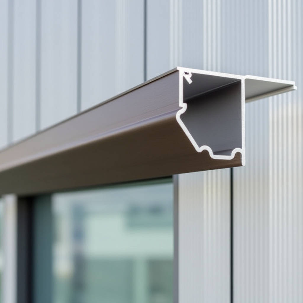
Water intrusion at the building envelope's most vulnerable transition points remains one of the most persistent and costly failure modes in commercial construction. When a curtain wall meets a window head, a parapet terminates at a roof membrane, or a cladding system transitions to a lower roof, the geometry creates a natural pathway for moisture. Aluminum Drip Flashing is the engineered solution that intercepts this pathway. Unlike generic sheet metal trim, properly specified aluminum drip flashing combines the metallurgical durability of solid aluminium with a profile geometry designed to break capillary action and direct water outward, away from the structural substrate. For architects and facade contractors working on mid-rise to high-rise commercial projects, the specification of drip flashing is not a finishing detail to be delegated to a sub-tier installer. It is a fundamental component of the drainage plane, and its material selection, coating system, and attachment method carry consequences that ripple through warranty claims, maintenance schedules, and long-term building performance.
Why Aluminum Drip Flashing Matters Beyond Code Minimums
Building codes mandate flashing at specific locations. The International Building Code (IBC) Section 1405.4 requires flashing at wall penetrations, intersections with roofs, and above openings. ASTM E2112 provides standard practice for installation. But meeting code minimums and achieving a 30-year watertight assembly are two different thresholds. The difference lies in three factors: material choice, profile design, and integration sequencing with the adjacent cladding and weather-resistive barrier (WRB).
Aluminum drip flashing fabricated from solid 5052-H32 or 3003-H14 aluminium sheet brings specific advantages to this equation. At 0.032 inch (0.81 mm) minimum thickness per AAMA 711-13 for commercial applications, and often specified at 0.040 inch (1.0 mm) or 0.050 inch (1.27 mm) for high-wind zones or coastal environments, solid aluminium provides a stiffness-to-weight ratio that roll-formed galvanized steel cannot match without adding significant mass. This matters when the flashing must maintain its drip leg geometry under thermal cycling, wind pressure, and the occasional impact from scaffolding or maintenance equipment.
The corrosion argument is equally important. Galvanized steel drip edges rely on a zinc coating that sacrifices itself over time. In coastal chloride environments, that sacrificial clock runs fast. Solid aluminium, particularly when paired with a PVDF coating system, does not rely on a sacrificial mechanism. The aluminium substrate forms a stable, self-limiting oxide layer. The PVDF topcoat provides UV resistance and color retention. Together, they deliver a service life that aligns with the 30-50 year design life expected of modern commercial curtain wall and cladding systems.
Profile Geometry: The Physics of Water Break
The term "drip flashing" covers a family of profiles, each engineered for a specific transition condition. Understanding the geometry is essential because specifying the wrong profile for a given condition creates a latent defect that may not manifest until the first driving rain after occupancy.
Standard Drip Edge (Type D)
The standard drip edge profile features a vertical leg that extends down the fascia, a horizontal flange that sits on the roof deck or substrate, and a pronounced outward kick at the bottom of the vertical leg. This kick, often called the "drip lip," is the critical feature. It must project far enough from the fascia plane to prevent water from tracking back via surface tension. A minimum 3/8-inch (10 mm) projection is common, but on projects with textured cladding surfaces or in regions with frequent wind-driven rain, a 1/2-inch (13 mm) projection provides a more reliable break.
Z-Flashing (Type Z)
Z-flashing serves horizontal transitions where one cladding plane steps back from another. The classic application is above window and door heads in a cavity wall or rainscreen assembly. The upper leg tucks behind the WRB or cladding above. The horizontal leg spans the cavity. The lower leg drops down over the head of the opening below. The geometry creates two 90-degree bends, forming the Z shape. Critically, the lower leg must include a drip lip or a hemmed edge. Without it, water running down the face of the flashing can curl back under the horizontal leg and enter the cavity.
Drip Cap with Backer Rod
Some manufacturers, including ClarkDietrich with their BackerBead product line, integrate a closed-cell foam backer rod into the upper flange of the drip flashing. This serves a dual purpose: it provides a compressible seal against the substrate above, and it creates a caulk tray that limits the depth of sealant applied at the top of the flashing. The backer rod prevents three-sided adhesion, which is a common cause of sealant joint failure. For aluminum drip flashing used above windows in a rainscreen system, this integrated backer rod detail can eliminate a separate installation step and reduce the risk of improper sealant tooling.
Coating Systems and Finish Specification
The coating on aluminum drip flashing is not decorative. It is a functional barrier that determines the component's resistance to UV degradation, chemical attack, and color shift over decades of exposure. Three coating tiers dominate the commercial specification landscape:
| Coating System | Resin Chemistry | AAMA Standard | Film Thickness | Typical Warranty | Best Application |
|---|---|---|---|---|---|
| PVDF (Kynar 500® / Hylar 5000®) | 70% PVDF resin, 30% acrylic | AAMA 2605 | 1.0-1.2 mil (25-30 μm) total | 20-30 years film integrity | Exterior cladding, drip edges, high-UV exposure |
| Super Durable Polyester | Polyester with TGIC/HAA crosslinker | AAMA 2604 | 2.0-2.4 mil (50-60 μm) | 10-15 years | Semi-exposed flashing, soffit applications |
| Standard Polyester | Polyester resin | AAMA 2603 | 0.8-1.0 mil (20-25 μm) | 5-7 years | Interior or fully sheltered conditions only |
| Mill Finish (Anodized) | AA-M10C22A31 (Class I) | AAMA 611 | 0.7 mil (18 μm) minimum | Varies by environment | Architectural interior, low-corrosion exterior |
For aluminum drip flashing exposed to direct sun and weather on a commercial facade, AAMA 2605-compliant PVDF is the specification that aligns with the service life of the adjacent solid aluminium cladding panels. The 70% PVDF resin content ensures that the coating does not chalk, fade, or lose adhesion within the building's expected maintenance cycle. Specifying anything less on an exposed drip edge creates a mismatch: the cladding panels will look new in year 15 while the flashing shows visible degradation.
Color matching between the drip flashing and the adjacent cladding panels is another specification point that deserves attention. PVDF coatings are applied in a spray-and-bake process. Batch-to-batch color variation is a reality, even with tight quality control. For critical sight lines, such as drip edges at a prominent parapet or a highly visible window head, specifying that the flashing and the cladding panels be coated in the same production run minimizes the risk of metameric mismatch under different lighting conditions.
Material Thickness and Wind Load Performance
Wind load is the primary structural load case for aluminum drip flashing. Unlike roof-mounted drip edges that see uplift, wall-mounted drip flashing at window heads and cladding transitions experiences both positive and negative wind pressure as wind flows around building corners and over parapets.
The thickness of the aluminium sheet directly determines the flashing's resistance to deflection and permanent deformation under wind load. A 0.032-inch (0.81 mm) thickness may be adequate for a 4-inch (100 mm) exposed leg in a sheltered urban location. But for a 6-inch (150 mm) exposed leg on a 20-story coastal tower, 0.050-inch (1.27 mm) or even 0.063-inch (1.60 mm) solid aluminium may be required to keep deflection within L/180 limits under the design wind pressure calculated per ASCE 7.
The attachment method interacts with thickness. Flashing secured with exposed fasteners through the face of the vertical leg will experience prying forces at each fastener location under negative wind pressure. Thicker material distributes these forces across a wider bearing area, reducing the risk of slotting or tear-out around the fastener holes. For projects where exposed fasteners are not acceptable architecturally, the flashing must be designed with a continuous cleat or receiver system that allows the visible leg to be snapped into place without face fasteners. This cleat system requires the flashing material to have sufficient spring temper to maintain engagement, another reason to specify 5052-H32 alloy with its higher yield strength compared to 3003-H14.
Integration with Rainscreen and Cavity Wall Systems
In a rainscreen assembly, the aluminum drip flashing serves as the horizontal termination of the drained and ventilated cavity. Its function is not just to shed water but to do so while maintaining the cavity's ventilation airflow. This requires careful detailing of the flashing's end dams, lap joints, and interface with the vertical cladding rails or support system.
At the head of a window opening in a rainscreen, the Z-flashing must extend past the rough opening by a minimum of 4 inches (100 mm) on each side. These extensions, or end dams, prevent water that reaches the flashing from running off the ends and into the opening. The end dams should be turned up at a 90-degree angle and sealed to the adjacent WRB with a compatible liquid-applied flashing or a high-performance tape such as a butyl-based product.
The lap joint between adjacent lengths of aluminum drip flashing is a common leak point. A minimum 3-inch (75 mm) lap is standard, with the upper piece lapping over the lower piece in the direction of drainage. The lap should be sealed with a bead of neutral-cure silicone or a strip of butyl tape. For PVDF-coated flashing, the sealant must be tested for adhesion to the specific coating formulation. Some silicone sealants exhibit poor adhesion to certain PVDF topcoats without a primer.
At the interface between the drip flashing and the solid aluminium cladding panels above, a minimum 3/8-inch (10 mm) gap must be maintained to allow for thermal expansion and to provide a drainage path. The flashing's upper leg should extend at least 2 inches (50 mm) behind the WRB or the cladding panel's rear face. This overlap is the primary defense against water that penetrates the cladding joints or runs down the face of the WRB.
Fabrication Tolerances and Quality Control
Aluminum drip flashing is typically fabricated by press brake forming from flat sheet stock. The dimensional tolerances that matter for installation are:
- Leg length tolerance: ±1/16 inch (±1.6 mm) for legs up to 6 inches (150 mm). For longer legs, ±1/8 inch (±3.2 mm).
- Bend angle tolerance: ±1 degree from specified. A 91-degree bend on a drip leg that should be 90 degrees will cause the leg to kick inward, potentially contacting the substrate and trapping water.
- Straightness: Maximum bow of 1/8 inch per 10 feet (3.2 mm per 3 meters) of length. Excessive bow makes it impossible to maintain a straight sight line at the drip edge.
- Hem edge uniformity: If the drip lip is hemmed (folded back on itself), the hem must be fully closed and uniform along the entire length. An open hem traps water and creates a corrosion initiation point.
For large commercial projects, it is advisable to require a first-article inspection: the fabricator produces one full-length piece of each flashing profile for review and approval before proceeding with production. This catches dimensional issues, coating defects, and color match problems before they affect hundreds of linear feet of material.
Common Installation Failures and How Specifications Prevent Them
Field investigations of water intrusion cases consistently reveal a short list of recurring installation errors related to aluminum drip flashing. Understanding these failures allows the specification writer to address them proactively.
Reverse lap at joints. When the lower piece of flashing laps over the upper piece, water running down the flashing hits the exposed edge of the lap and is driven into the joint rather than shed over it. The specification should state: "Lap flashing sections with upper piece overlapping lower piece. Minimum lap 3 inches. Seal lap with continuous bead of neutral-cure silicone sealant."
Missing or inadequate end dams. At the ends of a drip flashing run, water that reaches the flashing can simply run off the end and into the wall assembly. The specification should require end dams at all flashing terminations, turned up a minimum of 1 inch (25 mm) and sealed to the WRB.
Fastener penetration above the water line. Fasteners driven through the horizontal leg of a Z-flashing, above the point where the flashing turns down, create a direct path for water to enter the substrate. All fasteners should be located in the vertical leg below the horizontal bend, or in a concealed cleat behind the visible leg. The specification should include a diagram showing acceptable fastener locations.
Galvanic corrosion from dissimilar metal fasteners. Aluminum drip flashing secured with galvanized steel or plain steel fasteners will experience galvanic corrosion, particularly in coastal or industrial environments. The aluminum acts as the anode and corrodes preferentially around each fastener. The specification should require stainless steel fasteners (Type 304 or 316, depending on environment) or aluminum fasteners with a compatible coating.
Sealant bridging over the drip lip. When sealant is applied at the top of a drip flashing and tooled downward, it can bridge across the drip lip, creating a path for water to track back to the substrate. The specification should note that sealant must be tooled to terminate at the top of the drip lip, not wrap around it.
Specifying Aluminum Drip Flashing for International Projects
For procurement managers and facade contractors sourcing aluminum drip flashing for projects outside North America, several additional considerations apply. The ASTM and AAMA standards referenced in U.S. specifications may not be directly transferable to projects governed by EN, BS, or AS/NZS standards. The following equivalencies are useful:
- AAMA 2605 (PVDF) is roughly equivalent to EN 13523-25 for coating performance, but the specific test methods differ. A project specification should state the required standard explicitly rather than relying on assumed equivalency.
- Aluminium alloy 5052-H32 per ASTM B209 corresponds to EN AW-5052 H32 per EN 485. The mechanical properties are nearly identical.
- Sheet thickness specified in inches (U.S.) must be converted to millimeters for international procurement. 0.032 inch = 0.81 mm, 0.040 inch = 1.02 mm, 0.050 inch = 1.27 mm, 0.063 inch = 1.60 mm.
For projects in the Middle East, Southeast Asia, or other regions with extreme UV exposure and high ambient temperatures, the PVDF coating specification should include a requirement for heat-reflective pigments if the flashing color is dark. Dark-colored aluminum drip flashing in direct sun can reach surface temperatures exceeding 180°F (82°C), which accelerates coating degradation and increases thermal expansion. Cool pigment technology can reduce surface temperature by 20-30°F (11-17°C) without changing the visible color.
Suppliers such as Futeng® with manufacturing capabilities in solid aluminium fabrication can provide aluminum drip flashing in custom profiles, lengths, and PVDF color matches to coordinate with the project's cladding panel specification. When sourcing internationally, the procurement specification should require mill test reports for the aluminium coil, coating batch certificates, and dimensional conformance reports for each shipment.
Cost Factors and Value Engineering Considerations
Aluminum drip flashing represents a small fraction of a commercial facade budget, typically less than 1% of the total cladding cost. Value engineering that reduces the flashing specification to save cost is a false economy. The cost of replacing failed flashing on an occupied building, including access equipment, removal of adjacent cladding, and business interruption, can exceed the original flashing cost by a factor of 20 or more.
The primary cost drivers for aluminum drip flashing are:
- Material thickness: Moving from 0.032 inch to 0.050 inch increases material cost by approximately 55%, but the installed cost difference is much smaller because labor and access costs remain constant.
- Coating specification: PVDF (AAMA 2605) costs approximately 2-3 times more than standard polyester (AAMA 2603) per square foot of coated surface. For exposed flashing, this premium is non-negotiable.
- Profile complexity: A simple drip edge with two bends costs less to fabricate than a Z-flashing with hemmed edges and integrated end dams. However, the profile must match the technical requirement; simplifying the profile to save fabrication cost creates a performance gap.
- Custom color matching: Matching a custom architectural color adds a setup charge and may require a minimum order quantity. Specifying a standard color from the manufacturer's library avoids this cost.
The most cost-effective strategy is to standardize the flashing profiles across the project. A single Z-flashing profile that works at window heads, door heads, and horizontal cladding transitions reduces the number of fabrication setups and minimizes field errors from installing the wrong profile at the wrong location.
Quality Assurance During Installation
The best specification is worthless if the installed product does not match it. A quality assurance program for aluminum drip flashing installation should include the following checkpoints:
Before installation begins, verify that the delivered flashing matches the submittal: check the alloy, thickness, coating type, color, and profile dimensions against the approved shop drawings. Measure the drip lip projection with a caliper. Confirm that fasteners are the specified material and finish.
During installation, inspect the first 10 linear feet of each flashing type before the crew proceeds further. Check lap direction, lap length, sealant application, end dam installation, and fastener spacing. Document the inspection with photographs. If errors are found, correct them and re-inspect before allowing production to continue.
After installation, conduct a hose test or spray rack test on a representative section of the facade that includes the flashing. This test simulates wind-driven rain and can reveal leaks that are not visible during dry weather. The test should be conducted before the flashing is covered by subsequent cladding components, so that any leaks can be traced to their source and repaired.
For projects pursuing LEED, BREEAM, or other sustainability certifications, the aluminum drip flashing can contribute to credit achievement. Solid aluminium with a high recycled content (typically 50-70% for coil stock) supports Materials and Resources credits. The PVDF coating's long service life reduces the need for replacement and supports the Life-Cycle Assessment credit category.
Aluminum drip flashing is a deceptively simple component. Its geometry appears obvious, its material seems straightforward, and its cost looks negligible on a project budget. But the physics of water management at building transitions is unforgiving. A 1/8-inch error in drip lip projection, a reversed lap joint, or a fastener placed above the water line can channel thousands of gallons of water into a wall assembly over the building's service life. The specification must be precise, the fabrication must be accurate, and the installation must be verified. When these three conditions are met, aluminum drip flashing performs its function silently and invisibly for decades, which is exactly what a well-designed drainage component should do.
For facade engineers and procurement teams specifying aluminum drip flashing on commercial projects, the key takeaways are: specify PVDF coating per AAMA 2605 for all exposed applications, require 0.040-inch minimum thickness for commercial wall conditions with thicker material for high-wind or coastal zones, mandate stainless steel fasteners to prevent galvanic corrosion, include end dams at all terminations, and implement a first-article inspection and installation QA program. These requirements add minimal cost to the project while eliminating the most common failure modes that lead to water intrusion, warranty claims, and premature facade degradation.