Aluminum Coping Bracket Engineering for Wind Load and Thermal Movement in Parapet Design
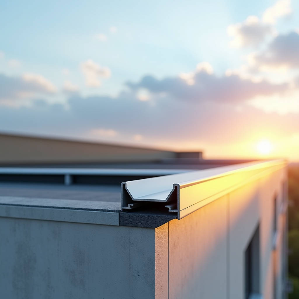
A parapet wall coping system is only as reliable as the hardware that holds it in place. The Aluminum Coping Bracket is that hardware—a structural anchor that transfers wind uplift, thermal movement, and dead load from the coping profile into the building substrate. When a coping panel lifts off during a storm, post-mortem investigations rarely point to the aluminum sheet itself. The failure almost always traces back to the bracket: wrong alloy, undersized gauge, insufficient fastener embedment, or a misalignment that introduced stress concentrations no coping profile was designed to handle. For contractors and specifiers working on mid-rise to high-rise commercial envelopes, understanding bracket engineering is not a detail to delegate. It determines whether the parapet stays watertight and intact through decades of thermal cycling and extreme wind events.
What Separates a Structural Bracket from a Simple Strap
Many aluminum coping systems on the market rely on thin-gauge straps that do little more than provide a friction fit for the coping profile. These straps are often punched from 1.2mm to 1.5mm aluminum sheet with no stiffening ribs, no positive mechanical lock, and no allowance for differential movement. They work adequately on low-rise residential parapets where wind suction rarely exceeds 1.0 kPa. The problem arises when the same hardware gets specified for a 20-story commercial tower where corner zone wind pressures can spike to 3.5 kPa or higher under ASCE 7-16 design criteria.
A properly engineered Aluminum Coping Bracket differs in several measurable ways. The material is typically 5052-H32 or 6061-T6 aluminum alloy, selected for its combination of corrosion resistance and yield strength. The bracket is formed with a continuous vertical leg that transfers shear into the substrate through a minimum of two fasteners per bracket, spaced to prevent rotational failure. The horizontal flange that receives the coping profile includes a positive engagement detail—either a folded return, a cleat geometry, or a spring-loaded clip—that resists uplift without relying solely on friction. Material thickness for commercial-grade brackets starts at 2.0mm and goes up to 3.0mm for wide coping profiles exceeding 300mm in projection.
Alloy Selection and Why It Matters
Not all aluminum is interchangeable. The marine-grade 5052 alloy commonly used in architectural sheet metal offers excellent corrosion resistance but has a lower tensile strength (approximately 210–260 MPa depending on temper) compared to 6061-T6, which can reach 310 MPa. For brackets that will be installed in coastal environments, 5052-H32 is often preferred because its magnesium content provides superior resistance to chloride-induced pitting. For inland applications where strength-to-weight ratio is the priority, 6061-T6 brackets allow thinner sections while maintaining load capacity.
The galvanic compatibility between bracket and coping profile also deserves attention. When a 6061-T6 bracket contacts a 3003-H14 coping profile, the small difference in electrochemical potential is negligible in most atmospheric conditions. However, if the bracket is secured with stainless steel fasteners, a thin nylon or EPDM isolation washer between the bracket and the fastener head prevents galvanic corrosion at the contact point. The American Architectural Manufacturers Association (AAMA) provides guidance on compatible metal pairings in AAMA 611-14, which covers voluntary specifications for anodized architectural aluminum.
Wind Load Transfer and Bracket Spacing Calculations
The spacing of aluminum coping brackets directly governs the wind resistance of the entire coping assembly. Standard practice places brackets at 600mm to 900mm centers, but this rule of thumb falls apart when parapet height, building exposure, and local wind climate are factored in. The correct approach starts with the design wind pressure for the specific building zone, calculated per ASCE 7 or the local building code equivalent.
For a parapet on a building with a mean roof height of 30 meters in Exposure Category C, the corner zone design pressure might reach 3.2 kPa (negative, acting upward). If the coping profile is 400mm wide, each linear meter of coping experiences an uplift force of 1.28 kN per meter. At 900mm bracket spacing, each bracket must resist 1.15 kN of uplift. At 600mm spacing, that drops to 0.77 kN per bracket. The bracket manufacturer should provide allowable load tables derived from physical pull-out testing, not just theoretical calculations. A bracket rated for 1.5 kN ultimate capacity with a safety factor of 2.0 has an allowable working load of 0.75 kN—making the 600mm spacing mandatory for this scenario.
Contractors should request bracket load test data that includes the failure mode: did the bracket itself deform, did the fasteners pull out of the substrate, or did the coping profile disengage from the bracket? The weakest link defines the system capacity. Futeng® aluminum coping brackets, for example, are tested with the full assembly—bracket, fastener, and substrate—because isolated component testing does not capture interaction effects.
Fastener Embedment and Substrate Considerations
The bracket is only as strong as its connection to the parapet wall. Concrete parapets require wedge anchors or sleeve anchors with minimum embedment depths of 50mm to 65mm, depending on the anchor diameter and concrete strength. For hollow CMU parapets, toggle bolts or chemical anchors with mesh sleeves are necessary to prevent pull-out through the thin face shell. Steel-framed parapets with plywood or DensGlass sheathing demand large-diameter wood screws or self-drilling screws into the steel stud flange, with edge distance requirements that often dictate bracket width.
A common field error is the use of powder-actuated fasteners (PAFs) into concrete for coping brackets. While PAFs are fast, their pull-out capacity in tension is highly variable and dependent on concrete aggregate, moisture content, and operator technique. Most bracket manufacturers explicitly exclude PAFs from their approved fastener schedules for tension applications. The ICC Evaluation Service (ICC-ES) publishes acceptance criteria for mechanical anchors in concrete (AC193) and adhesive anchors (AC308) that provide a reliable basis for fastener selection.
Thermal Movement Accommodation
Aluminum expands and contracts at approximately 0.000023 mm per mm per degree Celsius. A 3-meter coping length subjected to a 60°C temperature swing (from -10°C in winter to 50°C under direct summer sun) will change length by about 4.1mm. If the brackets restrain this movement rigidly, the coping profile will buckle, the bracket fasteners will loosen over repeated cycles, or the coping-to-bracket connection will fret and wear.
The bracket design must accommodate movement through one of two strategies. The first is a sliding connection: the bracket's horizontal flange allows the coping profile to slide longitudinally while maintaining vertical and lateral restraint. This requires a low-friction interface, often achieved with a thin PVC or nylon wear strip between the bracket and the coping. The second strategy is a fixed-and-sliding bracket arrangement: every other bracket is installed as a fixed point with a positive mechanical lock, while intermediate brackets act as sliding supports. This approach is detailed in the Metal Building Manufacturers Association (MBMA) guidelines for metal roof edge systems.
For parapets longer than 30 meters, expansion joints in the coping itself become necessary, and the bracket layout must coordinate with these joints. Each expansion joint requires a pair of brackets placed symmetrically about the joint line, with the coping sections terminating at those brackets and a separate joint cover piece spanning the gap.
Secret-Fix vs. Face-Fix Bracket Systems
The choice between concealed (secret-fix) and exposed (face-fix) bracket systems affects both aesthetics and long-term performance. Secret-fix systems use a click-in or snap-in bracket geometry that locks the coping profile from underneath, leaving the top surface unbroken. This eliminates exposed fastener penetrations through the coping, which are the primary entry points for water in face-fixed systems. The trade-off is that secret-fix brackets require tighter installation tolerances: the bracket must be level within 1-2mm across the parapet width, or the coping will not engage properly.
Face-fix brackets, where the coping is screwed or riveted through its top surface into the bracket, are simpler to install and allow for on-site adjustment. However, every fastener penetration is a potential leak path. If face-fix is specified, the fasteners must be fitted with EPDM sealing washers, and the coping profile should include a slight cross-fall (minimum 1:40 slope) to shed water away from the fastener heads. The table below summarizes the key performance differences.
| Parameter | Secret-Fix Bracket System | Face-Fix Bracket System |
|---|---|---|
| Water penetration risk | Low (no top-side penetrations) | Moderate to high (each fastener is a leak path) |
| Installation speed | Moderate (requires precise bracket alignment) | Fast (field-adjustable fastener positions) |
| Wind uplift resistance | High (mechanical interlock engages full profile width) | Moderate (dependent on fastener pull-over strength) |
| Thermal movement accommodation | Good (sliding interface inherent in design) | Limited (fasteners may restrict movement) |
| Typical bracket material thickness | 2.0–3.0mm aluminum | 1.5–2.5mm aluminum or stainless steel |
| Relative cost (material + labor) | Higher (precision manufacturing required) | Lower (simpler bracket fabrication) |
| Aesthetic outcome | Clean, uninterrupted coping surface | Visible fastener heads on coping face |
| Maintenance access | Requires special tool to disengage clips | Direct access to all fasteners |
Bracket Corrosion Protection and Coating Compatibility
Aluminum coping brackets are inherently corrosion-resistant, but they are not immune to degradation in aggressive environments. In coastal or industrial atmospheres, mill-finish aluminum will develop a white oxide layer that, while self-limiting, can cause aesthetic staining on adjacent materials and increase friction at the bracket-to-coping interface over time. Anodized brackets (AA-M10C22A31, Class I architectural anodizing per The Aluminum Association standards) provide a harder, more durable surface with minimal thickness build-up, making them suitable for sliding connections.
For projects where the bracket is partially visible—for example, at open-ended coping terminations or at expansion joints—a PVDF coating matched to the coping color may be specified. PVDF-coated brackets should use a chrome-based pretreatment rather than titanium-zirconium to ensure adhesion on the small-radius bends typical of bracket profiles. The coating thickness for brackets is typically a two-coat system (primer plus color coat) at 25–30 microns, rather than the three-coat 35–40 micron systems used on visible cladding panels, because the bracket does not face direct UV exposure in service.
Custom Brackets for Non-Standard Parapet Conditions
Standard off-the-shelf brackets assume a flat, level parapet top with the coping installed parallel to the roof plane. Real buildings rarely comply. Parapets with sloped tops for drainage, stepped parapets at elevation changes, curved parapets on radiused facades, and parapets with embedded lightning protection or snow retention systems all require bracket modifications.
For sloped parapets where the coping must maintain a level top line while the substrate falls, the bracket vertical leg is fabricated with a tapered shim plate or an adjustable threaded stem that allows the installer to dial in the bracket height. The adjustment range is typically ±15mm, sufficient for most drainage slopes. For curved parapets, brackets are supplied with a radius-matched flange profile, which requires the fabricator to have CNC folding capability rather than relying on standard press brake tooling. The minimum practical radius for a continuously curved coping with custom brackets is approximately 3 meters; tighter radii require segmented coping with mitered joints.
When specifying custom brackets, the lead time typically extends by 2–3 weeks compared to standard brackets. The engineering submittal should include shop drawings showing bracket dimensions, material grade, coating specification, and the bracket layout drawing keyed to the parapet plan. This is not a detail to leave to the installer's discretion on site.
Quality Verification Before Installation
Before brackets are installed, the general contractor or cladding subcontractor should perform a receiving inspection that goes beyond counting pieces. Check the bracket material thickness with a micrometer at several points—not just at the flat sections but at the bend radii, where thinning can occur during forming. Verify the alloy and temper against the mill certificate. For anodized brackets, check the coating thickness with an eddy-current gauge; for PVDF-coated brackets, use a DFT gauge calibrated for non-magnetic substrates.
A representative sample of brackets should be test-fitted with a short section of the actual coping profile to verify engagement force and alignment. If the coping clicks onto the bracket too easily, the mechanical interlock may be insufficient for wind resistance. If it requires excessive force, the installers will struggle on site, leading to incomplete engagement and potential blow-off. The target engagement force for a secret-fix bracket is typically 50–80 Newtons per linear meter of coping, measured with a spring scale during pull-off testing.
Installation Sequencing and Common Field Errors
The bracket installation sequence matters. Brackets should be set after the parapet waterproofing membrane is fully installed and tested, but before the coping profile is placed. Each bracket is positioned using a string line or laser level to ensure a consistent elevation across the parapet length. The tolerance is ±2mm in elevation and ±3mm in plan position relative to the parapet centerline. Brackets that are out of level will telegraph through the coping as visible waves or steps, especially on long straight parapets viewed against the sky.
The most persistent field error is over-tightening the bracket fasteners. When a wedge anchor in concrete is torqued beyond its rated value, the concrete around the anchor crushes locally, reducing pull-out capacity. When a self-drilling screw into a steel stud is over-torqued, the threads strip and the connection loses all tension capacity. The correct torque values are anchor-specific and should be listed on the bracket installation drawing. A calibrated torque wrench is not optional equipment for coping bracket installation.
Another common mistake is mixing fastener types on the same bracket. If one leg of the bracket is secured with a stainless steel wedge anchor and the other with a zinc-plated screw, the galvanic couple will accelerate corrosion of the less noble fastener. All fasteners on a given bracket should be of the same material and finish, and that material should be compatible with the aluminum bracket per the galvanic series chart published in ASTM G82.
Long-Term Performance and Maintenance Inspection
An aluminum coping bracket system, correctly specified and installed, should deliver a service life of 30 years or more with minimal intervention. The coping profile itself may require recoating after 20–25 years depending on PVDF coating performance, but the brackets, being shielded from UV and direct weather, generally outlast the coping. Annual visual inspections should check for coping displacement, loose or missing sections, and any signs of water staining on the parapet interior face that might indicate a failed bracket connection.
After major storm events, a targeted inspection of corner and edge parapet zones is warranted. These zones experience the highest wind suction, and a bracket that has partially disengaged may not be visible from ground level. A gentle upward pressure applied to the coping edge with a pry bar will reveal any loose sections before they become airborne hazards.
For projects in hurricane-prone regions, the bracket system should be specified and tested to meet ANSI/SPRI ES-1, the standard for wind design of edge systems used with low-slope roofing. This standard, referenced by the International Building Code, requires physical testing of the complete edge assembly—coping, brackets, and fasteners—under simulated wind pressures with a factor of safety of 2.0 against failure. Compliance with ES-1 is not automatically achieved by using ES-1-tested coping profiles; the bracket and fastener combination must be tested as a system. The Single Ply Roofing Industry (SPRI) maintains a directory of ES-1 compliant systems.
Specifying an Aluminum Coping Bracket that meets the structural, thermal, and corrosion demands of the project is not a cost-saving exercise. It is an exercise in risk allocation. The bracket represents a small fraction of the total facade cost—typically less than 2%—but a bracket failure can result in water damage claims, falling debris liability, and curtain wall performance failures that dwarf the initial hardware cost. For procurement managers and facade engineers, the bracket specification deserves the same level of scrutiny as the visible aluminum panels it supports.