Aluminum Expansion Joint Profile Engineering for Thermal and Seismic Facade Performance
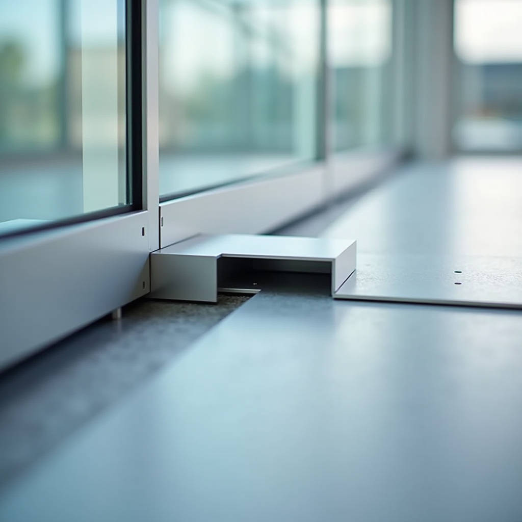
When a multi-storey parking structure in Dubai experiences daily thermal swings of 25°C, the difference between a facade that buckles and one that performs flawlessly often comes down to a single component: the Aluminum Expansion Joint Profile. Specifying these profiles is not a matter of ticking a box on a submittal sheet. It requires understanding how extruded aluminum geometries interact with live loads, seismic drift, and the relentless expansion-contraction cycles that define building envelopes in extreme climates. This article examines the engineering logic behind profile selection, the material science of 6063-T5 and 6061-T6 alloys, and the installation practices that separate a 30-year service life from premature failure at the joint.
Why Aluminum Dominates the Expansion Joint Conversation
Steel expansion joint covers have been around for decades. Stainless steel still holds a place in heavy industrial settings. But walk through any recently completed commercial tower, airport terminal, or hospital atrium, and the expansion joint profiles you see spanning floor-to-floor transitions and facade breaks are overwhelmingly aluminum. The reason is not cost alone.
Aluminum extrusion technology allows manufacturers to produce complex, multi-chamber profiles with integrated anchoring legs, ball-and-socket articulation points, and snap-in cover plates — all from a single billet. A 6063-T5 alloy extruded profile with a 2.5mm wall thickness can achieve a yield strength of 145 MPa while weighing roughly one-third of an equivalent steel section. This strength-to-weight ratio matters when you are installing 6-meter lengths of joint cover at height, where every kilogram adds to the handling burden and the dead load transferred to the substructure.
Corrosion resistance is the second factor. Aluminum forms a self-passivating oxide layer that eliminates the need for hot-dip galvanizing or epoxy coating that steel profiles demand. In coastal environments — think Doha, Miami, or Singapore — anodized aluminum profiles with AA20 or AA25 coating thickness withstand salt spray for decades without the red rust that eventually finds its way through scratched steel coatings. The Aluminum Association's anodizing standards provide detailed guidance on coating specifications for architectural applications.
Reading the Engineering Numbers Behind Joint Movement
Every expansion joint profile has a rated movement capacity, typically expressed as a percentage of the nominal joint width. A profile rated for ±50% movement installed in a 50mm joint can accommodate a total range of 25mm to 75mm. But the real question is whether that rating holds up under the specific conditions of your project.
Thermal movement in aluminum curtain wall systems follows a straightforward formula: ΔL = α × L × ΔT, where α for aluminum is 23.1 × 10⁻⁶ per °C. A 30-meter uninterrupted aluminum facade section subjected to a 60°C temperature range (from -10°C winter night to +50°C summer solar gain) will expand by approximately 41.6mm. If the expansion joint profile specified for that facade break cannot absorb that displacement, the stress transfers into the cladding panels themselves, potentially causing fastener tear-out or panel oil-canning.
Seismic movement adds another dimension. Unlike thermal movement, which is largely predictable and unidirectional within a given cycle, seismic drift is multi-directional and sudden. The Aluminum Expansion Joint Profile must accommodate not just axial extension and compression, but also lateral shear and vertical offset. This is where the ball-and-socket articulation found in systems like the Novojunta Pro Metal series becomes critical. The spherical joint allows the cover plate to rotate independently of the base frame, maintaining a flush walking surface or a clean visual line even when the two sides of the joint are momentarily misaligned by 15mm or more.
Profile Geometry and Load-Bearing Logic
Not all aluminum expansion joint profiles are designed to carry traffic. The distinction between pedestrian-rated, vehicle-rated, and non-load-bearing profiles is fundamental, and getting it wrong has consequences ranging from trip hazards to catastrophic cover plate collapse.
Floor joint profiles intended for pedestrian traffic typically feature a top flange thickness of 3.0mm to 5.0mm in aluminum, with reinforcing ribs spaced at 150mm to 300mm intervals along the extrusion. The cover plate must resist point loads of at least 2.5 kN (roughly equivalent to a person with luggage) without permanent deformation. Profiles rated for vehicular traffic — common in multi-storey car parks and loading docks — push this requirement to 5.0 kN or higher, and often incorporate a secondary support beam beneath the visible cover plate.
The PROPLATE FIX range from Progress Profiles illustrates the flat-joint approach: a minimalist aluminum cover that sits flush with the finished floor, relying on the rigidity of the extrusion itself rather than a visible frame. This works well in retail and commercial interiors where the joint should be as inconspicuous as possible. The trade-off is that flat profiles generally offer less vertical movement capacity than their raised counterparts, making them suitable primarily for interior applications where temperature and humidity swings are moderate.
For exterior facade joints, the profile geometry shifts toward deeper sections with integrated drainage channels. Water ingress through a facade expansion joint is not just a nuisance — it can saturate insulation, corrode steel backup framing, and create the conditions for freeze-thaw damage in colder climates. The best aluminum expansion joint profiles for exterior walls incorporate a dual-seal system: an external EPDM or silicone gasket that deflects the majority of wind-driven rain, and an internal labyrinth or cavity that depressurizes any moisture that penetrates the first line of defense.
Material Specifications That Matter
The alloy and temper of the aluminum extrusion directly affect the profile's structural performance, corrosion resistance, and suitability for different finishing processes. For architectural expansion joint profiles, the industry has largely settled on two alloys:
| Property | 6063-T5 | 6063-T6 | 6061-T6 |
|---|---|---|---|
| Tensile Strength (MPa) | 150 | 205 | 290 |
| Yield Strength (MPa) | 110 | 170 | 240 |
| Elongation (%) | 8-10 | 8 | 8-10 |
| Corrosion Resistance | Excellent | Excellent | Very Good |
| Anodizing Quality | Superior | Good | Moderate |
| Typical Application | Interior joints, light traffic | Exterior facade, medium traffic | Heavy traffic, parking decks |
6063-T5 is the workhorse of the architectural aluminum industry. It extrudes beautifully, accepts anodizing with exceptional color uniformity, and provides adequate strength for most interior and sheltered exterior applications. When the profile needs to span wider joints or carry heavier loads, 6063-T6 offers a meaningful strength upgrade without sacrificing the surface finish quality that architects expect.
6061-T6 enters the conversation when the expansion joint must handle vehicular loading or when the profile doubles as a structural element. Its higher strength allows for thinner sections that still meet load requirements, but the trade-off is a slightly coarser grain structure that can show through anodized finishes. For this reason, 6061-T6 profiles in visible locations are often powder-coated rather than anodized. The ASTM B221 standard governs the dimensional tolerances and mechanical properties of extruded aluminum bars, rods, wire, profiles, and tubes, and should be referenced in every project specification.
Surface Finishing and Long-Term Weathering
The aluminum expansion joint profile is only as durable as its surface treatment. Anodizing and PVDF (polyvinylidene fluoride) coating are the two dominant finishing technologies, and they serve fundamentally different purposes.
Anodizing is an electrochemical process that converts the aluminum surface into a controlled oxide layer. Architectural anodizing to AA20 or AA25 (20-25 microns) provides excellent abrasion resistance and a metallic appearance that many architects prefer for interior applications. However, anodized aluminum exposed to direct sunlight and pollution will eventually develop a chalky appearance as the oxide layer weathers. In coastal environments, the chloride ions in sea spray can pit anodized surfaces if the coating thickness is insufficient or if the anodizing process was not properly sealed.
PVDF coating, applied as a liquid spray and oven-cured, offers superior color retention and chemical resistance for exterior applications. A properly applied PVDF system consists of a chrome-based conversion coating, a corrosion-inhibiting primer (5-8 microns), and a color topcoat (25-30 microns), for a total dry film thickness of 30-38 microns. This three-coat system, when applied to aluminum expansion joint profiles for exterior facades, can maintain color stability and gloss retention for 20-30 years, as validated by AAMA 2605 testing protocols.
For projects where the expansion joint profile must match the surrounding cladding panels exactly — a common requirement in high-end commercial facades — PVDF is the preferred route. Suppliers like Futeng® who control both the aluminum panel fabrication and the PVDF coating line can achieve consistent color matching across flat panels and extruded profiles, eliminating the subtle shade variations that occur when profiles are sourced separately from panels.
Installation Details That Prevent Callbacks
The most meticulously engineered Aluminum Expansion Joint Profile will fail if it is installed without accounting for the actual joint width at the time of installation. This sounds obvious, but it is one of the most frequent sources of post-installation problems.
Aluminum expansion joint profiles are typically manufactured for a specific nominal joint width, but the actual gap on site can vary by ±10mm or more depending on the quality of the concrete work or steel erection. Installing a profile at the wrong temperature — when the building structure is at its maximum thermal expansion, for example — can consume the profile's movement capacity before the building is even occupied. The rule of thumb is to install expansion joint profiles at the median expected temperature for the location, so that the profile has roughly equal movement capacity in both the expansion and contraction directions.
The anchoring system deserves equal attention. Profiles that rely on mechanical fasteners into concrete must use anchors rated for cracked concrete conditions, as the edges of expansion joints are precisely where cracking is most likely to initiate. Stainless steel anchors (316 grade for coastal environments, 304 for interior) eliminate the risk of galvanic corrosion between the aluminum profile and the steel fastener. The ISO 15836 series provides comprehensive guidance on the design and installation of expansion joints in buildings.
Watertight Systems for Parking Decks and Podiums
Multi-storey car parks and podium decks present a unique challenge: the expansion joint must accommodate structural movement while preventing water — often contaminated with road salt and oil — from leaking through to occupied spaces below. This is where watertight aluminum expansion joint profiles with integrated EPDM or TPV gaskets become essential.
A typical watertight floor joint system consists of an aluminum base frame anchored to both sides of the structural gap, a flexible EPDM membrane that spans the joint and is mechanically clamped into the frame, and an aluminum cover plate that protects the membrane from traffic wear. The membrane is the critical element: it must remain flexible at temperatures as low as -30°C, resist ozone degradation, and maintain its sealing integrity through millions of movement cycles.
Testing these systems is not optional. A watertight expansion joint profile should be tested to a minimum of 1.0 bar (10 meters of water column) under both static and dynamic conditions. Dynamic testing — where the joint is cycled through its full movement range while under water pressure — is particularly revealing because it exposes weaknesses in the clamping mechanism that static testing misses. The ASTM E283 standard for air leakage testing is often referenced alongside water penetration standards for a complete performance picture.
Specifying for Seismic Zones
In seismic zones — which now include not just the well-known Pacific Rim but also regions of the Middle East, Southern Europe, and parts of the Eastern United States — the expansion joint profile must do more than just open and close. It must handle lateral shear, vertical offset, and sometimes rotational movement, all while maintaining life-safety functionality.
Seismic-rated aluminum expansion joint profiles are characterized by wider cover plates that maintain coverage even when the two sides of the joint are offset by 50mm or more. The cover plate is typically mounted on a sliding mechanism that allows it to remain centered over the joint regardless of the direction of movement. Some systems use a pantograph-style linkage beneath the cover plate to maintain alignment; others rely on a spring-loaded centering mechanism.
The key specification parameter for seismic joints is the movement rating expressed as a percentage of joint width. A joint rated for 100% movement in a 100mm gap can accommodate 200mm of total displacement. But for seismic applications, the specifier should also look at the multi-directional movement capacity: a profile that handles ±50mm axially but only ±10mm laterally may be inadequate for a building expected to experience significant drift.
In practice, seismic joint specifications should be reviewed by the structural engineer of record, who can correlate the profile's movement capacity with the calculated inter-story drift from the seismic analysis model. No expansion joint profile, regardless of its rating, can compensate for a joint width that is fundamentally undersized for the expected movement.
Cost Drivers and Value Engineering
The cost of an Aluminum Expansion Joint Profile is influenced by several factors beyond the raw aluminum price. Extrusion die complexity is a major one: a simple flat cover profile requires a relatively inexpensive die and extrudes at high speed, while a complex multi-chamber profile with integrated anchoring legs and gasket grooves requires a more expensive die, extrudes more slowly, and generates more scrap during setup.
Finishing costs scale with the profile's visible surface area. Anodizing costs are relatively linear — larger profiles cost proportionally more to anodize. PVDF coating costs are influenced more by the number of color changes required; a project specifying 50 different colors for expansion joint profiles will pay a significant premium over one using a single standard color.
Installation labor is the hidden cost driver. A profile that arrives on site pre-assembled with gaskets installed and anchoring clips pre-attached will install in a fraction of the time required for a system that must be assembled piece by piece. The Schluter-DILEX-STF system, with its pre-drilled and pre-aligned brackets, is an example of design-for-installation thinking that reduces site labor. When evaluating bids, the installed cost — material plus labor — is the only meaningful comparison metric.
Quality Verification Before Shipment
For procurement managers and QA/QC engineers, verifying the quality of aluminum expansion joint profiles before they leave the factory is far cheaper than discovering problems on site. The inspection checklist should cover:
- Dimensional verification: Profile cross-sections measured against the approved shop drawing, with tolerances per ASTM B221. Wall thickness at critical load-bearing points checked with an ultrasonic gauge.
- Alloy verification: Positive material identification (PMI) using handheld XRF or OES equipment to confirm the alloy composition matches the mill certificate. A 6063 profile mistakenly supplied as 6061 will be weaker than specified; the reverse will be stronger but may have finishing issues.
- Coating adhesion: Cross-hatch adhesion testing per ASTM D3359 for PVDF coatings. Anodizing thickness measurement using eddy current instruments.
- Straightness: Profiles should be checked for bow and twist, particularly for long lengths (3 meters and above). A profile with a 5mm bow over 3 meters will create installation difficulties and may not seat properly in its anchoring system.
- Assembly fit: For multi-component systems, a random sample of assemblies should be test-fitted to verify that cover plates snap into base frames with the specified force and that gaskets seat properly in their grooves.
Documentation should include mill test certificates for the aluminum billets, coating performance test reports, and a certificate of conformance stating that the profiles meet the specified ASTM, AAMA, or ISO standards. For projects requiring third-party verification, an independent inspection agency can be engaged to witness the testing and sign off on the shipment.
Making the Right Call for Your Project
Specifying an Aluminum Expansion Joint Profile is ultimately an exercise in matching the profile's capabilities to the project's specific demands. There is no universal "best" profile — only the profile that is right for the joint width, movement requirements, traffic conditions, exposure environment, and aesthetic expectations of the building in question.
Start with the numbers: calculate the expected thermal movement, verify the seismic drift requirements, and determine whether the joint will see pedestrian traffic, vehicle traffic, or no traffic at all. Then select the alloy, finish, and profile geometry that meets those numbers with a reasonable safety margin. Finally, verify the installation conditions — joint width at time of installation, anchor type, and ambient temperature — and document them so that the as-built conditions are recorded for future reference.
The aluminum expansion joint profile is a small component in the total bill of materials for a building envelope. But its failure can trigger a cascade of problems — water ingress, cracked finishes, trip hazards, and in the worst case, damage to the structural frame itself. The engineering attention it deserves is proportional not to its cost, but to the consequences of getting it wrong.