Aluminum Corner Cleat Engineering for Solid Aluminium Rainscreen Facades Load Distribution and Failure Prevention
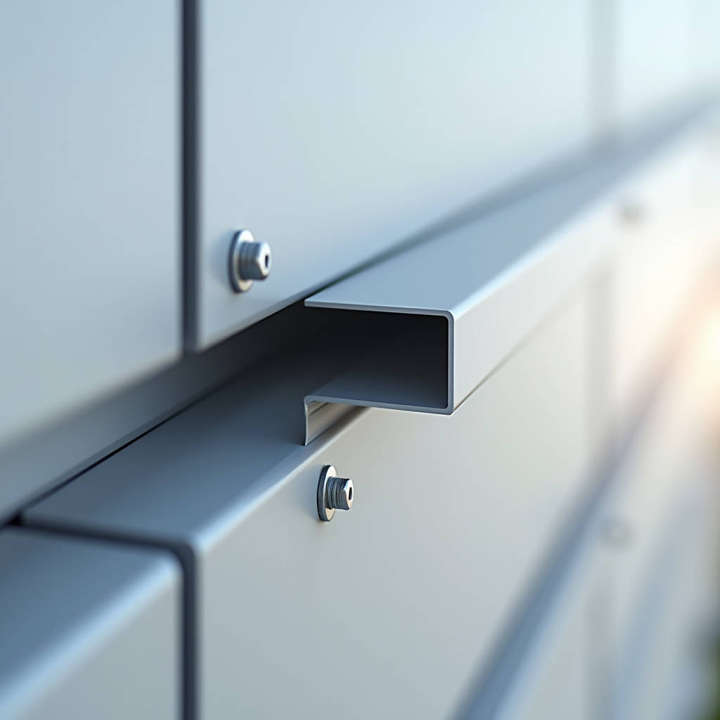
On a rainscreen façade, the visible surface gets all the attention. Architects spend months selecting panel finishes, joint widths, and shadow gaps. But the components hidden behind the cladding—the ones nobody sees after handover—often determine whether a building envelope performs for 15 years or fails in 5. The Aluminum Corner Cleat sits squarely in that category. It is a small, typically L-shaped bracket fabricated from extruded or machined aluminium, used to secure solid aluminium cladding panels at external corners, window reveals, soffit transitions, and parapet edges. Its job sounds simple: hold the panel in place while accommodating thermal movement, wind suction, and the dead load of a 2.5mm or 3.0mm thick solid aluminium sheet. In practice, getting this right means understanding bearing stress, slot geometry, fastener shear capacity, and the difference between a cleat that merely fits and one that actually works over a 30-year service life. This article examines the engineering logic behind aluminium corner cleats for solid cladding systems, the failure modes that contractors encounter on site, and the procurement decisions that separate a watertight façade from a costly remedial headache.
What Separates a Structural Cleat from a Simple Bracket
Not every L-shaped piece of aluminium deserves the name "structural cleat." In rainscreen and façade engineering, the term implies a component that transfers specific loads—dead load from the panel mass, wind load (positive and negative pressure), and occasionally seismic or blast loads—into the building's primary structure or secondary framing grid. A genuine structural Aluminum Corner Cleat differs from a generic bracket in three measurable ways: material grade, cross-sectional geometry, and the presence of slotted holes engineered for differential movement.
Material grade matters more than many procurement managers assume. Extruded cleats made from 6063-T6 aluminium offer yield strengths around 170 MPa, while 6061-T6 extrusions push that figure to approximately 240 MPa. For a 3.0mm thick solid aluminium panel measuring 1,200mm × 900mm, the panel alone weighs roughly 8.7 kg. Add wind suction on a high-rise (design pressure of 2.5 kPa on a corner zone), and the pull-out force on each cleat connection becomes significant. A cleat fabricated from an unknown recycled alloy with inconsistent mechanical properties might hold during installation but creep or fracture under sustained cyclic loading. The extrusion die design—specifically the internal radius where the two legs of the cleat meet—also governs stress concentration. A sharp internal corner creates a stress riser that can initiate cracking long before the nominal yield stress is reached anywhere else in the part.
Slot geometry is the third differentiator. A properly engineered cleat for solid aluminium cladding includes an elongated hole on at least one leg, oriented parallel to the expected direction of thermal expansion. Aluminium expands at roughly 0.024 mm per metre per degree Celsius. A 3-metre tall panel on a south-facing façade in Dubai can experience a surface temperature swing of 60°C between a winter night and a summer afternoon. That translates to approximately 4.3 mm of linear expansion. If the cleat constrains this movement rigidly, the stress manifests as panel buckling, fastener fatigue, or—in the worst case—cleat fracture at the bend line.
Why Corner Cleats Fail on Solid Aluminium Rainscreens
Site investigations of failed cladding systems reveal recurring patterns. The cleat itself rarely fails first. Instead, the failure cascade typically starts at the interface between the cleat and the panel, or between the cleat and the supporting subframe. Understanding these mechanisms helps contractors specify the right product and install it correctly.
Galvanic Corrosion at the Fastener Interface
When a stainless steel self-tapping screw passes through an aluminium cleat into a steel subframe, three dissimilar metals sit in electrical contact. Add rainwater—especially in coastal or industrial environments where chlorides or sulphates act as electrolytes—and galvanic corrosion becomes inevitable. The aluminium, being the most anodic of the three, sacrifices itself. Within two to three years, the area around each fastener hole turns to white oxide paste, and the clamping force disappears. The cleat remains physically present but structurally useless.
The standard mitigation is a physical barrier: a nylon or EPDM isolation washer between the stainless fastener head and the aluminium cleat, plus a nylon bush or sleeve inside the hole itself. This breaks the metallic circuit. Some manufacturers, including Futeng®, supply cleats with pre-applied isolation layers as part of a complete solid aluminium cladding system, which eliminates the risk of site teams forgetting this step. The cost difference between an isolated cleat assembly and a bare one is negligible—perhaps $0.15 per unit—but the rectification cost of a corroded corner connection on a 20-storey tower runs into six figures.
Undersized Bearing Area
A cleat leg that is too short or too narrow concentrates the panel's dead load onto a tiny area of the supporting rail. Aluminium, even at T6 temper, has a bearing strength of approximately 260 MPa for 6061-T6. If a 30 mm wide cleat leg bears on a 3 mm thick rail flange, the bearing area is 90 mm². A panel weighing 8.7 kg exerts a downward force of about 85 N at that point, which is well within limits. But the same cleat under wind suction of 2.5 kPa on a 1.08 m² panel area experiences a pull-out force of 2,700 N. The bearing stress jumps to 30 MPa, which is still acceptable. The problem emerges when the cleat leg is only 15 mm wide because someone specified a smaller part to save money—bearing stress doubles to 60 MPa, and the safety factor erodes rapidly once cyclic loading and material fatigue enter the picture.
Thermal Expansion Lock-Up
This failure mode is the most insidious because it takes years to manifest. A cleat installed with round holes instead of slotted holes, or with slotted holes oriented in the wrong direction, prevents the panel from expanding and contracting freely. The panel itself buckles—visible as a subtle wave or oil-canning effect across the façade. The cleat, meanwhile, experiences cyclic bending stress every day as the sun moves across the building. After several thousand thermal cycles, the aluminium at the bend line work-hardens and eventually cracks. The panel then becomes partially unsecured, rattles in the wind, and eventually detaches at the corner.
Material Selection: Extruded vs. Fabricated Cleats
Procurement teams face a choice between two manufacturing routes for aluminium corner cleats: extruded profiles cut to length and machined, or sheet metal fabrications bent from flat plate. The decision affects cost, lead time, mechanical properties, and long-term durability.
| Parameter | Extruded 6063-T6 Cleat | Extruded 6061-T6 Cleat | Fabricated 5052-H32 Cleat |
|---|---|---|---|
| Yield Strength (MPa) | 170 | 240 | 193 |
| Ultimate Tensile Strength (MPa) | 215 | 290 | 228 |
| Elongation (%) | 10 | 10 | 12 |
| Corrosion Resistance (Coastal) | Good | Good | Excellent (marine-grade) |
| Typical Leg Thickness (mm) | 3.0 – 6.0 | 3.0 – 6.0 | 2.0 – 4.0 |
| Tooling Cost | High (custom die) | High (custom die) | Low (standard tooling) |
| Unit Cost (per 1000 units) | Medium | Medium-High | Low-Medium |
| Lead Time | 4-6 weeks (die fabrication) | 4-6 weeks (die fabrication) | 2-3 weeks |
| Best Application | Standard rainscreen corners | High-load, high-rise corners | Low-rise, moderate-load corners |
The data above reflects real-world procurement scenarios. Extruded cleats offer superior consistency in cross-section and mechanical properties because the extrusion process aligns the grain structure along the length of the profile. Fabricated cleats, bent from 5052-H32 sheet, exhibit work-hardening at the bend line—the bend itself becomes stronger than the flat legs, but the grain structure is disrupted, and micro-cracks can initiate at the outer radius if the bend is too tight. The rule of thumb: the internal bend radius should be at least equal to the material thickness. For a 3.0 mm thick fabricated cleat, the minimum internal radius is 3.0 mm. Tighter bends risk cracking that may not be visible to the naked eye but will propagate under service loads.
Engineering the Slot: Movement Accommodation Done Right
The elongated hole on a corner cleat is not a manufacturing convenience—it is a critical engineering feature. Getting the slot dimensions wrong has consequences that ripple through the entire façade system.
A properly designed slot on an Aluminum Corner Cleat must account for the total expected movement range of the panel relative to the subframe. This includes thermal expansion, as discussed, but also moisture-related movement (minor for aluminium but significant for any backing materials), building frame deflection under live load, and seismic drift in relevant zones. The slot length should equal the maximum expected movement plus the fastener diameter, plus a safety margin of at least 2 mm on each side. For a 3-metre panel with 4.3 mm of thermal movement, using an M6 fastener (6 mm diameter), the minimum slot length works out to 4.3 + 6 + 4 = 14.3 mm. Specifying a 16 mm slot provides a comfortable margin.
The slot orientation is equally important. On the leg that attaches to the panel, the slot should run parallel to the panel's long axis—the direction of maximum thermal expansion. On the leg that attaches to the subframe, the slot orientation depends on the subframe's own movement characteristics. Vertical subframe members expand vertically; horizontal rails expand horizontally. The cleat must accommodate both, which sometimes requires slots on both legs, oriented 90° to each other.
Fastener selection within the slot matters. A standard hex-head bolt with a flat washer can bind against the slot edges if the washer diameter exceeds the slot width. A better approach uses a flange-head fastener or a bolt with a reduced-diameter washer specifically sized for the slot. The fastener should be tightened to a torque that allows the panel to slide under thermal movement but prevents rattling under wind buffeting. This "snug-tight" condition—typically around 50-60% of the full tightening torque for the fastener size—requires skilled installers who understand the difference between "tight" and "locked."
Wind Load Distribution at Building Corners
Corner zones on any building experience significantly higher wind pressures than the general wall area. The ASCE 7-22 standard defines corner zones (Zone 5) where negative pressure coefficients can reach -2.8 on the wall surface, compared to -0.9 for the field of the wall. This means a corner cleat on a high-rise must handle roughly three times the suction load of a cleat in the middle of the façade.
For a solid aluminium panel at the building corner, the cleat arrangement must reflect this reality. A typical field panel might use four cleats—two at the top, two at the bottom—each carrying roughly 25% of the panel's wind load. At the corner, the same panel might require six cleats, with the two additional units placed along the vertical edge closest to the building corner. The cleat spacing along that edge should not exceed 400 mm centre-to-centre for panels in high-wind zones, based on testing by façade engineering consultancies.
The AAMA 508-14 standard for pressure-equalized rainscreen systems provides guidance on fastener and cleat spacing, though it does not prescribe exact values for every configuration. The underlying principle is that the cleat-to-panel connection must resist the design wind load with a safety factor of at least 3.0 against ultimate failure. For a design wind pressure of 2.5 kPa on a corner zone, each cleat connection must therefore withstand 7.5 kPa without pull-out, tear-out, or permanent deformation. This is not a theoretical exercise—it is the difference between a façade that stays intact during a 50-year storm and one that sheds panels onto the street below.
Coating Compatibility and Long-Term Durability
Most solid aluminium cladding panels arrive on site with a factory-applied PVDF (polyvinylidene fluoride) coating, typically 25-35 microns thick for a two-coat system or 35-45 microns for a three-coat system with a clear topcoat. The corner cleat, being a separate component, often arrives mill-finish or with a basic anodized layer. This mismatch creates a subtle but real durability concern.
An uncoated aluminium cleat in contact with the back face of a PVDF-coated panel does not create a galvanic problem—both are aluminium. But the cleat itself, exposed to the cavity air behind the rainscreen, will oxidize over time. In a benign inland environment, the natural oxide layer that forms on aluminium is self-limiting and protective. In a coastal or industrial environment, the oxide layer can become pitted, and the cleat's cross-sectional thickness gradually reduces. After 20 years, a 3.0 mm thick cleat leg might measure 2.5 mm in places, and the bearing capacity drops accordingly.
The solution is to specify cleats with a minimum anodized finish—Class I architectural anodizing per AAMA 611-14, with a coating thickness of at least 15 microns (AA-M10C12A21). This adds roughly $0.08-0.12 per cleat and extends the component's service life to match the 25-30 year expected life of the PVDF-coated panels. For projects within 5 km of a coastline, a marine-grade anodized finish or a thin PVDF coating on the cleat itself is worth the incremental cost.
Futeng® supplies corner cleats as part of their solid aluminium cladding package with the option of matching the cleat finish to the panel specification, which eliminates the mismatch entirely. This is particularly relevant for projects where the cavity behind the rainscreen is ventilated and the cleats are partially visible through open joints.
Procurement Pitfalls: What to Check Before Signing the PO
Procurement managers buying aluminium corner cleats for a large cladding project face a market flooded with options that look identical in a catalogue photograph but differ dramatically in dimensional accuracy, material certification, and traceability. The following checks separate a supplier worth trusting from one that will cause problems on site.
Mill certificates. Every batch of extruded cleats should come with a material test certificate from the extrusion mill, stating the alloy designation, temper, and the results of mechanical testing (yield strength, tensile strength, elongation). A supplier that cannot provide these certificates—or provides certificates that list only "aluminium" without a specific alloy grade—is selling material of unknown provenance. For a project requiring 5,000 cleats, the cost of a single independent laboratory test on a random sample is approximately $200-300. That is cheap insurance.
Dimensional tolerance. An extruded cleat with a specified leg length of 50 mm should measure 50 mm ± 0.5 mm. A fabricated cleat bent from sheet might have a tolerance of ± 1.0 mm on the leg length and ± 1.5° on the bend angle. Tolerances that are looser than this create cumulative alignment problems across a façade. By the time the 50th panel is installed, a 1.5° angle error on each cleat has pushed the corner out of plane by several millimetres.
Slot consistency. Slotted holes should be punched or milled, not drilled by hand. A hand-drilled slot has rough edges that create stress concentrations and can cut into the fastener shank over time. The slot edges should be deburred and smooth to the touch. If the sample cleat has sharp edges anywhere, the entire batch is suspect.
Packaging and traceability. Cleats should arrive in clearly labelled boxes indicating the alloy, temper, batch number, and production date. This level of traceability matters when a problem emerges on site three years later and the contractor needs to determine whether the affected cleats came from a specific batch. A supplier that ships cleats loose in a cardboard box with no labelling is not a supplier to trust with a multi-million-dollar façade project.
Installation Sequence: The Difference Between Aligned and Acceptable
Even the best-engineered Aluminum Corner Cleat performs poorly if installed out of sequence or with incorrect torque. The following installation workflow, developed from site experience on solid aluminium rainscreen projects across the Middle East, Southeast Asia, and North America, reduces the risk of misalignment and fastener damage.
- Set out the subframe grid first. All vertical and horizontal rails must be installed, surveyed, and confirmed within tolerance (± 2 mm over any 3-metre span) before any cleat touches the building. Adjusting cleats to compensate for a crooked subframe transfers stress into the panel.
- Pre-fit cleats to the panel in the factory or at ground level. Attaching cleats to the back of the panel before lifting it into position is faster and more accurate than trying to fit them at height. Use a jig to ensure consistent positioning—each cleat should be located within ± 1 mm of the specified position.
- Lift the panel into position and engage the cleats with the subframe. Insert fasteners through the slotted holes but do not tighten fully. The panel should be able to slide within the slots.
- Align the panel to the adjacent panels. Use shims or temporary wedges to achieve the specified joint width (typically 10-20 mm for open-joint rainscreens, 6-8 mm for silicone-sealed joints).
- Tighten fasteners to the specified torque. Use a calibrated torque wrench, not an impact driver. Impact drivers over-tighten fasteners, crushing the cleat against the subframe and eliminating the movement capacity that the slot was designed to provide.
- Verify a random sample. After installation, check at least 5% of cleats for correct torque, proper isolation washer placement, and evidence of the panel's ability to slide within the slot. Document the checks.
When to Specify a Custom Cleat vs. an Off-the-Shelf Part
Standard corner cleats—the 50 mm × 50 mm × 3 mm L-bracket with a single slot on each leg—work for the majority of solid aluminium cladding applications. But certain conditions demand a custom-engineered solution.
Parapet and coping details. The top edge of a building is exposed to the highest wind suction and the most severe thermal cycling. A standard cleat may not provide enough bearing area or enough movement capacity. A custom cleat with a longer slot and a thicker leg section (5 mm or 6 mm instead of 3 mm) is often justified for these locations.
Curved or faceted façades. When the building corner is not a clean 90° but a radius or a series of short facets, the cleat must accommodate the specific angle. Variable-angle cleats, where the two legs are joined by a pivot rather than a fixed bend, allow the installer to adjust the angle on site. These are more expensive—roughly 3-5 times the unit cost of a fixed-angle cleat—but they eliminate the need for dozens of custom die sets.
Seismic zones. In regions classified as Seismic Design Category D or higher under IBC 2021, the cleat must accommodate not only thermal movement but also inter-story drift. This requires slots that are significantly longer than the thermal-only calculation suggests, and the fastener must be designed to slide within the slot without binding during a seismic event. A nylon glide bushing inside the slot reduces friction and prevents galling between the aluminium cleat and the stainless fastener.
Quality Assurance: Testing What Matters
Façade consultants and building envelope engineers increasingly require physical testing of cladding connections, including corner cleats, before approving a system for installation. The relevant test standards depend on the project location, but the following are commonly referenced:
- ASTM E330 / E330M: Structural performance of exterior windows, doors, skylights, and curtain walls by uniform static air pressure difference. This test applies positive and negative pressure to a mock-up of the cladding system and measures deflection and permanent deformation. A corner cleat assembly should show no permanent deformation after cycling to 1.5 times the design wind pressure.
- CWCT (Centre for Window and Cladding Technology) Standard: Widely used in the UK and Middle East, this standard requires a full-scale mock-up test including the corner cleat connections. The test sequence includes air permeability, water penetration (static and dynamic), and wind resistance.
- ISO 16283-3:2016: While primarily an acoustic standard, it references the structural integrity of façade components, which indirectly governs cleat performance under vibration and cyclic loading.
A practical recommendation: for any project exceeding 10,000 m² of solid aluminium cladding, commission a racking test on a mock-up that includes the specific corner cleat design. The test should cycle the mock-up through at least 5,000 pressure cycles (representing 50 years of wind loading) and verify that no cleat has loosened, cracked, or lost clamping force. The cost of this test—typically $15,000 to $30,000—is a fraction of the cost of replacing failed cleats on a completed building.
Integrating Cleats into a Complete Cladding System
An Aluminum Corner Cleat does not function in isolation. It is one component in a chain that includes the solid aluminium panel, the subframe rails, the thermal isolation pads, the fasteners, and the sealants or gaskets. A failure at any link in this chain compromises the entire corner connection. This is why some façade contractors prefer to source cleats from the same supplier that provides the panels and subframe—the compatibility is engineered rather than assumed.
When the panel, cleat, and subframe come from a single source, the slot dimensions on the cleat are matched to the hole pattern on the subframe, the fastener diameter is specified to suit both, and the isolation details are designed as a system rather than cobbled together from separate catalogues. This approach reduces the number of interfaces where a procurement error can introduce a mismatch. For contractors managing projects across multiple countries with different local supply chains, the simplicity of a single-source system has tangible value in reducing site coordination and RFI volume.
The solid aluminium cladding market has matured significantly over the past decade. Architects now specify 3.0 mm thick panels as standard for high-rise work, PVDF coatings in custom colours, and open-joint rainscreen systems that demand precise engineering at every connection point. The corner cleat, once an afterthought specified by the installer rather than the designer, has become a component that merits its own line item in the façade specification. Getting it right—material grade, slot geometry, corrosion protection, and installation torque—is not complicated, but it requires attention to detail that separates a watertight, durable façade from one that keeps a maintenance contractor busy for years.