Aluminum Mullion Extension Engineering Thermal Performance and Field Installation for Curtain Wall Systems
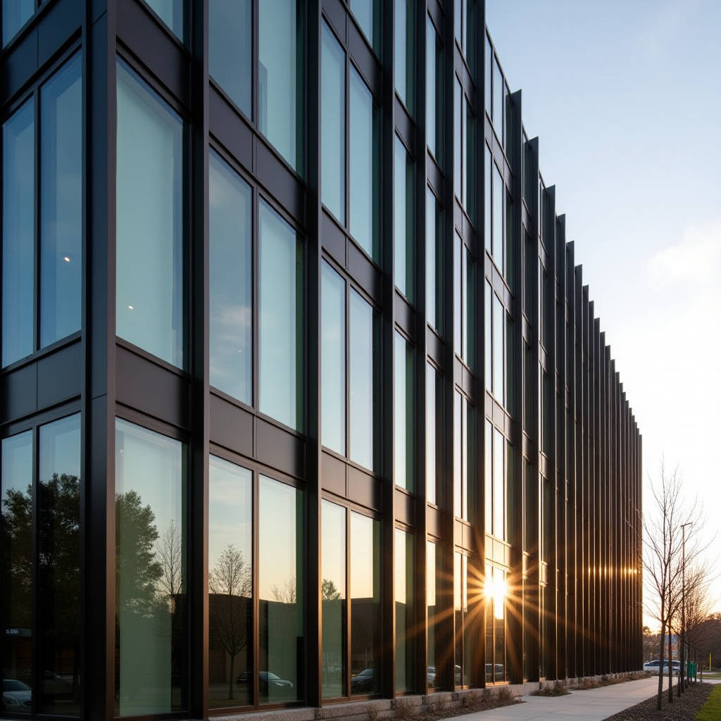
When a curtain wall project calls for extended sightlines, deeper shadow reveals, or bridging structural gaps between the building envelope and interior framing, the Aluminum Mullion Extension becomes a decisive component. This is not a generic trim piece. It is a load-path-critical extrusion that directly affects thermal performance, water management, and the long-term geometric stability of the entire facade assembly. Architects specifying deep-reveal window walls and contractors coordinating dimensional tolerances across floor slabs both need the same thing: an extension that holds its profile under differential movement without compromising the drainage plane. Getting that right means understanding alloy selection, fastening strategy, and the real-world fabrication limits that shop drawings rarely discuss.
What an Aluminum Mullion Extension Actually Does in a Facade System
In stick-built curtain wall and window wall assemblies, the primary vertical mullion transfers dead load and wind load from the glazing back to the building structure. An Aluminum Mullion Extension bolts or clips to the face or back of that primary mullion, extending its depth. The extension can serve several distinct functions depending on where it sits in the assembly. On the exterior side, it deepens the shadow line between vision glass and spandrel panels, creating the pronounced vertical rhythm that defines many contemporary commercial facades. On the interior side, it bridges the gap between the curtain wall plane and interior partition walls, eliminating the awkward drywall return that otherwise collects dust and complicates baseboard installation.
The structural logic is straightforward but frequently misunderstood. The extension itself is not a standalone load-bearing member. It relies on the primary mullion for stability and transfers any additional wind load back through the mechanical connection. This means the fastener spacing, the bearing surface between the extension and the parent mullion, and the torsional stiffness of the extension profile all interact. A deep extension with insufficient screw engagement or a slotted connection that allows rotation will telegraph movement into the gasket line, and that is where leaks begin.
Most commercial systems use 6063-T5 or 6063-T6 alloy for extensions, with wall thicknesses ranging from 0.064 inches (1.6 mm) to 0.125 inches (3.2 mm) depending on the projection depth and wind load requirements. The T5 temper is common for standard applications, but when the extension projects more than 6 inches from the primary mullion face, many engineers specify T6 for the additional yield strength, particularly in high-wind zones. Extrusions are typically supplied in 24-foot stock lengths, though some manufacturers offer custom cut-to-length services that reduce field labor and scrap.
Thermal Bridging and the Mullion Extension Problem
One of the most persistent performance issues in aluminum-framed facades is thermal bridging through continuous metal elements. A standard Aluminum Mullion Extension made from a single solid extrusion creates a direct conductive path from the exterior to the interior. In cold climates, this manifests as condensation on the interior face of the extension during winter months. In hot climates, the same path transfers solar heat inward, increasing cooling loads.
The industry has addressed this through several strategies. The most effective is the thermal break: a polyamide or polyurethane strip mechanically crimped between two separate aluminum extrusions. When applied to mullion extensions, the thermal break sits between the primary mullion and the extension profile, interrupting the conductive path. Some manufacturers offer pre-assembled thermally broken extension systems where the polyamide strip is factory-installed, eliminating the need for field assembly and ensuring consistent thermal performance across the entire elevation.
For projects targeting LEED or Passive House certification, the thermal performance of mullion extensions becomes a specification-level concern. The U-factor of the overall assembly includes the extension's contribution, and a non-thermally-broken extension can degrade the whole-window U-factor by 0.05 to 0.15 BTU/hr·ft²·°F depending on the projection depth and the ratio of extension surface area to total frame area. This is not a trivial number when the energy model is already tight. Specifying a thermally broken extension or using a polyamide clip system that minimizes metal-to-metal contact can recover most of that loss.
Expansion Mullions Versus Fixed Extensions: When Movement Matters
Not all mullion extensions are rigidly fixed. In long curtain wall runs, thermal expansion and inter-story drift demand accommodation. This is where the expansion mullion concept intersects with extension design. A male expansion mullion slides within a female receiver, allowing the facade to grow and shrink without buckling the aluminum or shearing fasteners. When an extension is attached to an expansion mullion, the extension itself must either be segmented to move with each bay or designed with a slip joint that maintains the visual line while absorbing movement.
CRL-U.S. Aluminum and similar suppliers offer male expansion mullions with integrated weather seals in stock lengths up to 24 feet 2 inches, typically in 6063-T5 alloy with custom paint finishes. These profiles are designed for storefront and low-rise curtain wall applications where movement accommodation is required by code. The weather seal is critical: without it, the sliding joint becomes a direct air and water path. The seal must maintain contact through the full range of design movement, which for a 20-foot mullion in a climate with a 100°F seasonal temperature swing can exceed 0.25 inches of linear expansion.
For solid aluminum cladding panel applications, the interaction between mullion extensions and panel attachment is particularly important. Cladding panels are typically fixed to the curtain wall framing with adjustable brackets that allow for fabrication and erection tolerances. If the mullion extension sits behind the panel plane, the bracket must clear the extension profile, which can force the panel further from the structural face and increase the dead load moment on the bracket. Coordination between the extension geometry and the cladding attachment system is a detail that should be resolved in shop drawings, not in the field.
Material Specifications and Finish Compatibility
The base material for architectural mullion extensions is almost always 6063 aluminum alloy, selected for its extrudability, corrosion resistance, and anodizing response. The T5 temper (cooled from an elevated temperature shaping process and artificially aged) provides a yield strength of approximately 16 ksi (110 MPa), which is adequate for most extension applications. T6 temper (solution heat-treated and artificially aged) raises yield strength to roughly 25 ksi (172 MPa) and is preferred for deep projections or hurricane zones.
Finish options fall into three categories: anodized, painted, and mill finish. Anodized extensions (typically Class I architectural anodizing per AAMA 611) provide a durable, UV-stable surface with a metallic appearance, but color consistency across multiple extrusion batches can be challenging. Painted finishes, most commonly 70% PVDF (polyvinylidene fluoride) liquid coatings meeting AAMA 2605, offer a wider color range and better batch-to-batch consistency. For solid aluminum cladding panels in 2.0 mm, 2.5 mm, or 3.0 mm thicknesses with PVDF coatings, matching the mullion extension finish to the panel finish is essential for a cohesive facade appearance. Futeng® supplies solid aluminum panels with PVDF coatings in a range of gloss levels and custom colors, and coordinating the extension finish with the panel specification early in the procurement process avoids visible mismatch on the completed elevation.
Mill finish extensions are the most economical but should be limited to interior applications or fully concealed conditions. Uncoated 6063 aluminum will develop a natural oxide patina that is generally uniform but not aesthetically controlled. For exterior applications, mill finish is rarely acceptable to architects and should be specified only with explicit written approval.
| Finish Type | Standard | Typical Thickness | Color Consistency | Relative Cost | Best Application |
|---|---|---|---|---|---|
| Class I Anodized | AAMA 611 | 0.7-0.8 mil (18-20 μm) | Moderate; batch variation | $$ | Exterior, metallic aesthetic |
| 70% PVDF Liquid | AAMA 2605 | 1.2-1.5 mil (30-38 μm) | Excellent; tight tolerances | $$$ | Exterior, custom color matching |
| Powder Coat (Polyester) | AAMA 2604 | 2.0-4.0 mil (50-100 μm) | Good; limited metallic options | $$ | Exterior, standard colors |
| Mill Finish | N/A | N/A | None; natural oxide | $ | Interior or concealed only |
Installation Sequence and Tolerance Stack-Up
Field installation of an Aluminum Mullion Extension looks straightforward on paper: align the extrusion, fasten at the specified spacing, seal the joints. In practice, the accumulated tolerances from the concrete slab, the anchor channel, the primary mullion bracket, and the primary mullion itself can easily consume the adjustment range built into the extension connection. When the extension is expected to align with interior partition walls or ceiling grids, the tolerance stack becomes a coordination problem that spans multiple trades.
The most reliable installation sequence begins with a surveyed grid. Before any extensions are cut or installed, the primary mullion positions should be verified against the building grid lines. Any deviation exceeding 1/8 inch over a 20-foot span should be corrected at the anchor level before extensions are attached. Extensions are then cut to length in the field, accounting for the thermal expansion gap at each end. A typical gap is 1/8 inch per 10 feet of extension length, but the specific value should come from the system manufacturer's thermal movement calculation.
Fastener selection deserves more attention than it typically receives. Stainless steel screws (Type 304 or 316 for coastal environments) are standard, but the thread type matters. Self-drilling screws with a sealing washer are common for attaching extensions to primary mullions, but the screw must be long enough to engage the full thickness of the extension wall plus at least three full threads into the primary mullion. Undersized screws or excessive torque can strip the aluminum, creating a loose connection that will work itself free under wind-induced vibration.
Water Management at Extension Joints
Water penetration through mullion extension joints is a failure mode that facade consultants see repeatedly in forensic investigations. The joint between the extension and the primary mullion, and the butt joints between adjacent extension lengths, are both potential entry points. The standard defense is a continuous sealant bead applied to the mating surfaces before assembly, but sealant alone is not a drainage strategy.
The better approach is a two-stage joint: an outer seal that acts as a rain screen, and an inner drainage cavity that collects and redirects any water that bypasses the outer seal. This requires the extension profile to include an integral drainage channel or a weep slot at the bottom of each bay. The weep must be sized to handle the expected water volume without clogging from dust or insect debris. A minimum weep opening of 3/16 inch by 1 inch is a common starting point, but projects in heavy-rain climates may need larger openings or more frequent weeps.
At the horizontal joint between extension segments, a silicone-compatible backer rod should be installed behind the sealant to control the sealant depth and prevent three-sided adhesion. The sealant joint width should be at least four times the expected movement, which for a 20-foot extension in a temperate climate is typically around 1/4 inch. This means a minimum sealant joint width of 1 inch, which is wider than many standard extension profiles accommodate without a custom joint detail.
Coordinating Mullion Extensions with Solid Aluminum Cladding Panels
When solid aluminum cladding panels are part of the facade system, the mullion extension often serves as the attachment substrate or the visual frame around the panel perimeter. This creates a geometric relationship that must be resolved in three dimensions. The panel face sits proud of the extension face by the thickness of the panel plus the bracket offset. The panel edge returns toward the extension, and the gap between the panel edge and the extension face is typically filled with a gasket or sealant.
The panel thickness drives the bracket offset. For 2.0 mm solid aluminum panels, the bracket can be relatively compact. For 3.0 mm panels, the additional weight and stiffness require a more robust bracket, which may push the panel further from the extension face. This offset affects the shadow line depth and the visual proportion of the vertical joints. Architects should review this dimension in a full-scale mockup, as drawings cannot convey the perceptual impact of a 1/4-inch change in reveal depth.
Panel flatness also interacts with extension alignment. Solid aluminum panels, particularly in larger formats, can exhibit oil-canning (visible waviness) under certain temperature and stress conditions. If the panel edge is held rigidly by the extension-mounted bracket, thermal expansion of the panel skin can induce compressive stress that manifests as distortion. The bracket design should allow for in-plane panel movement while restraining out-of-plane deflection. This is typically achieved with slotted bracket holes and a sliding connection at the panel return leg.
Code Compliance and Testing Standards
The performance of an Aluminum Mullion Extension within a curtain wall assembly is governed by a hierarchy of standards. At the top is the project's specified design wind load, typically derived from ASCE 7 in the United States or the relevant national wind code elsewhere. The extension, as part of the mullion assembly, must resist this load without exceeding allowable stress limits for the alloy and temper, and without deflecting more than L/175 (or the project-specified limit) at the design load.
Testing is conducted on the complete assembly, not on the extension in isolation. ASTM E283 (air infiltration), ASTM E331 (water penetration under static pressure), and ASTM E330 (structural performance under uniform static air pressure) are the standard test methods for curtain wall systems in North America. The extension's contribution to air and water performance is tested indirectly: if the extension joint leaks or the extension deflects excessively, the assembly fails. For impact-rated systems, ASTM E1886 and ASTM E1996 apply, and the extension must maintain its connection to the primary mullion through the impact and cyclic pressure loading sequence.
AAMA 501.4 and AAMA 501.6 provide additional guidance on recommended static and dynamic testing for curtain wall systems, including the evaluation of mullion connections. For projects in seismic zones, AAMA 501.4 is particularly relevant, as it subjects the assembly to inter-story drift that can disengage a poorly designed extension connection.
Supply Chain and Lead Time Considerations
Mullion extensions are custom extrusions in most cases. While some standard profiles are available from stock (particularly for storefront systems), architectural projects with unique depth requirements or custom finish specifications will require a die run. The extrusion die itself is a significant upfront cost, typically $2,000 to $5,000 depending on the profile complexity and the extruder. This die cost is amortized over the project quantity, and for large projects, it becomes a negligible line item. For small projects, it can be a budget shock.
Lead times for custom extrusions range from 6 to 12 weeks from die approval, plus finishing time. Anodizing adds 2 to 3 weeks. PVDF painting adds 3 to 4 weeks, including pretreatment and curing. Shipping from the extrusion plant to the fabrication shop and then to the job site adds another 1 to 2 weeks depending on geography. Total lead time from purchase order to job site delivery can easily reach 16 to 20 weeks for a custom-finished extension. This timeline must be integrated into the project schedule early, as extensions are typically needed early in the facade installation sequence.
For solid aluminum cladding panels sourced from manufacturers like Futeng®, coordinating the panel lead time with the extension lead time ensures that both components arrive on site in the correct installation sequence. Panels are typically installed after the curtain wall framing and extensions are in place, so a delay in extensions cascades directly into a delay in panel installation and overall facade completion.
Common Failure Modes and How to Avoid Them
Field experience reveals several recurring problems with mullion extensions. The most frequent is fastener pull-out, where the screw connecting the extension to the primary mullion strips the aluminum threads under wind load cycling. The fix is straightforward: specify the correct screw diameter and thread engagement, and use a torque-limiting driver during installation to prevent over-tightening. A stripped screw in aluminum cannot be re-tightened; the hole must be drilled out and tapped for a larger fastener, which is a field repair that no one wants on their punch list.
Galvanic corrosion is another concern, particularly in coastal or industrial environments. The contact between the aluminum extension and stainless steel fasteners is generally compatible, but if the fasteners are carbon steel (even zinc-plated), galvanic corrosion will attack the aluminum around the fastener hole. The specification should explicitly require stainless steel fasteners and should prohibit carbon steel in any component that contacts the aluminum extension.
Creep and stress relaxation in the aluminum itself can cause problems over time. Aluminum under sustained stress at elevated temperatures can deform permanently, loosening the connection. This is relevant for extensions in south-facing facades in hot climates, where surface temperatures can exceed 150°F. The design stress in the extension should be kept well below the alloy's yield strength at the maximum expected service temperature, with a safety factor of at least 1.5 on yield for sustained load conditions.
The Aluminum Mullion Extension is a component that rewards careful specification and punishes casual assumptions. When the alloy, finish, thermal strategy, and fastening details are all aligned with the project's performance requirements, the extension performs invisibly for decades. When any one of these factors is overlooked, the extension becomes the weak link in a facade system that otherwise meets every specification on the submittal. The difference between these two outcomes is engineering attention at the detail level, applied early enough to influence procurement and fabrication, not just field installation.
For project teams evaluating mullion extension options, the practical takeaway is to treat the extension as an engineered component rather than a commodity extrusion. Review the structural calculations for the specific profile and alloy. Specify the finish to match adjacent cladding panels under the same lighting conditions. Detail the joints for water management, not just for appearance. And coordinate the lead time with the overall facade procurement schedule so that the extensions arrive when the installers need them, not when the schedule says they should have arrived. These steps do not add cost relative to the risk they mitigate; they simply require the discipline to ask the right questions before the extrusion die is cut.