Interlocking Aluminum Bracket Engineering for Solid Cladding Facades Load Paths and Thermal Slip
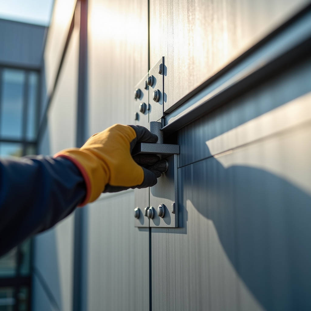
When a facade panel detaches at 30 meters above street level, the failure rarely traces back to the panel itself. The extrusion, the coating, the alloy temper — these hold. What gives way is the connection. The bracket. Specifically, the absence of a properly engineered interlocking aluminum bracket system that accounts for thermal displacement, wind suction, and the relentless micro-movements that tall buildings endure every day. An interlocking aluminum bracket is not a commodity accessory. It is a load-path component that determines whether a ventilated rainscreen performs for 40 years or becomes a liability in four. This article examines the engineering logic behind these brackets, the installation sequence that governs their performance, the corrosion mechanisms that degrade them, and the procurement decisions that separate durable facades from costly remedial projects.
What Defines an Interlocking Aluminum Bracket in Facade Engineering
In rainscreen and curtain wall assemblies, the term "interlocking aluminum bracket" refers to a two-part mechanical connection system. One half — typically the wall-side bracket — anchors to the building substrate through thermal isolation pads or direct fasteners. The other half — the panel-side bracket — attaches to the rear face of a solid aluminum cladding panel via stud welding, riveting, or adhesive bonding. The two halves engage through a geometric interlock: a male-female profile, a Z-clip interface, or a dovetail slide mechanism. Unlike simple angle brackets that rely entirely on fastener shear strength, an interlocking design transfers dead load and wind load through bearing contact between the two bracket halves. This matters because when wind suction peaks at 3.5 kPa on a corner zone of a high-rise, the bracket interface experiences combined tension and shear. A properly machined interlocking aluminum bracket distributes that force across the full contact surface rather than concentrating it at a bolt hole.
The material specification for these brackets is not arbitrary. Extruded 6063-T6 or 6005A-T6 aluminum alloys dominate the market. These alloys deliver yield strengths between 170 and 240 MPa while maintaining the corrosion resistance needed for exterior exposure. The T6 temper indicates solution heat treatment followed by artificial aging, which produces a fine precipitate structure that resists stress corrosion cracking. For coastal installations, some manufacturers specify 6082-T6 alloy with slightly higher magnesium content for improved pitting resistance. The bracket thickness typically ranges from 3.0 mm to 5.0 mm, with the thicker sections reserved for heavy panels exceeding 25 kg per square meter or for zones with high wind loads.
Thermal Dynamics: Why Interlocking Geometry Matters More Than You Think
A solid aluminum panel measuring 3,000 mm in length expands by approximately 2.0 mm for every 30°C temperature swing. Across a Dubai summer day, the panel surface temperature can shift from 25°C at dawn to 85°C under direct solar radiation. That is a 4.0 mm linear expansion. If the bracket connection locks the panel rigidly at both ends, the panel buckles. If the connection is too loose, the panel rattles during wind gusts. The interlocking aluminum bracket resolves this through controlled slip planes. The two halves of the bracket engage with a deliberate clearance — typically 0.5 mm to 1.0 mm — that allows the panel-side bracket to slide along the interlock axis while maintaining full bearing engagement in the load direction. This is not a flaw. It is a designed degree of freedom.
Engineers specify this slip capacity based on the panel's coefficient of thermal expansion (23.6 × 10⁻⁶ /°C for 3003-series aluminum) multiplied by the maximum expected temperature differential and the panel's unrestrained length. A bracket positioned at the panel's fixed point — usually the center — uses a tight interlock with minimal clearance. Brackets at the panel edges use the full slip range. The installation sequence must respect this hierarchy. A common failure mode observed in remedial investigations involves installers tightening all brackets identically, eliminating the slip capacity and forcing thermal stress into the panel edges. The result: oil-canning, fastener fatigue, and eventually, fracture at the bracket-to-panel connection.
Wind Load Engineering and Bracket Spacing Calculations
The interlocking aluminum bracket layout on a facade is not a matter of convenience. It is a structural calculation that begins with the project's wind load data. Using ASCE 7-22 or EN 1991-1-4, the design wind pressure for a given building zone determines the tributary area each bracket must support. For a solid aluminum panel measuring 1,200 mm × 3,000 mm with a design wind pressure of 2.8 kPa (suction), the total force per panel reaches 10.08 kN. If the panel uses six brackets — three along each long edge — each bracket carries 1.68 kN in tension or shear, depending on orientation.
Bracket manufacturers publish allowable load tables derived from testing per AAMA 501.4 and ASTM E330. A typical extruded interlocking aluminum bracket with a 100 mm engagement length might carry an allowable tension load of 2.5 kN with a safety factor of 3.0. The engineer checks that the applied load does not exceed the allowable, then verifies the fastener pull-out capacity in the substrate, the bracket's bending strength, and the interlock's bearing stress. On corner zones, where wind suction can be 1.5 to 2.0 times the field pressure, bracket spacing tightens. Where a field zone might use brackets at 600 mm centers, corner zones may require 400 mm or even 300 mm centers. This is not conservative overkill. It is what the numbers demand.
Corrosion: The Hidden Degradation Mechanism
Aluminum does not rust, but it corrodes. In facade applications, the dominant threats are galvanic corrosion and crevice corrosion. Galvanic corrosion occurs when an interlocking aluminum bracket contacts a dissimilar metal — typically a stainless steel fastener — in the presence of an electrolyte. Rainwater, condensation, or coastal salt spray completes the circuit. The aluminum, being more anodic than stainless steel, sacrifices itself. Over years, the bracket's interlock surface loses material, increasing the clearance and reducing bearing capacity. The fix is straightforward: isolate the fastener from the bracket using a nylon or EPDM washer, and specify fasteners made from 316-grade stainless steel rather than 304 in marine environments.
Crevice corrosion is subtler. It develops in the narrow gap between the two halves of the interlocking aluminum bracket where moisture becomes trapped and stagnant. The oxygen-depleted zone inside the crevice becomes anodic relative to the exposed surfaces, and localized pitting begins. The interlock geometry itself creates the crevice. Mitigation strategies include specifying anodized brackets (minimum 15 microns per AAMA 611) or applying a chromate conversion coating before installation. Some manufacturers, including Futeng®, supply brackets with a factory-applied PVDF coating matched to the panel finish, which provides both aesthetic continuity and additional corrosion resistance. The coating thickness on brackets should match the panel specification: 25-35 microns for standard architectural applications, per AAMA 2605.
Installation Sequence and Quality Control
The best interlocking aluminum bracket performs poorly if installed out of sequence. The correct workflow begins with setting out the bracket positions using a laser level or total station, not a tape measure. A deviation of 3 mm in bracket position at floor 10 becomes 15 mm by floor 25. Each bracket's wall-side half is fixed first, with shims used to achieve a coplanar mounting surface. The panel-side brackets are then attached to the panel in the factory or at a ground-level assembly area, not on the scaffold. This ensures the stud welding or riveting is performed in controlled conditions with proper quality checks.
During panel installation, the rigger engages the panel-side bracket into the wall-side bracket and allows the panel to settle under its own weight. The interlock should engage with an audible or tactile confirmation. Installers should never force the engagement with a hammer — this distorts the interlock geometry and can initiate cracks in the extruded profile. After engagement, a verification step confirms that the panel is free to slide along its slip axis. A simple manual push test suffices. If the panel resists movement, the bracket clearance is insufficient, and the installation must be corrected before proceeding.
Quality control documentation should include a bracket pull-out test on 1% of installed brackets, randomly selected, using a calibrated hydraulic tester. The test load should reach 1.5 times the design load without displacement exceeding 2 mm. Results are recorded against the bracket ID and panel location for traceability. This data becomes invaluable if a facade problem emerges years later and the investigation team needs to determine whether the failure originated in the bracket, the fastener, or the substrate.
Comparative Analysis: Interlocking Brackets vs. Conventional Fixing Methods
The choice between interlocking aluminum brackets and conventional angle-bracket systems is not simply about unit cost. It is about installation speed, long-term maintenance liability, and thermal performance. The table below compares four common fixing approaches for solid aluminum cladding panels on a typical mid-rise commercial facade.
| Parameter | Interlocking Aluminum Bracket | Conventional Angle Bracket | Face-Fixed Rivet | Structural Adhesive Only |
|---|---|---|---|---|
| Installation Speed (panels/day/team) | 18-25 | 12-16 | 8-12 | 6-10 |
| Thermal Movement Accommodation | Engineered slip plane (0.5-1.0 mm) | Slotted holes only | None — rigid constraint | Dependent on adhesive elasticity |
| Wind Load Capacity (per fixing, kN) | 2.0-3.5 | 1.5-2.5 | 1.0-1.8 | 0.8-1.5 (creep-limited) |
| Concealed Appearance | Yes — fully hidden | Partial — bracket visible at edges | No — fastener heads exposed | Yes — fully hidden |
| Replaceability of Single Panel | Lift-off disengagement | Requires adjacent panel removal | Drill-out required | Destructive removal only |
| Relative Installed Cost (per m²) | Baseline | -10% to -15% | -25% to -35% | -5% to +10% |
| Corrosion Risk (coastal) | Low (with isolation details) | Moderate (fastener contact) | High (exposed fasteners) | Low (no metal interface) |
| Typical Service Life (years) | 35-50 | 25-35 | 15-25 | 20-30 |
The data shows that while interlocking aluminum brackets carry a moderate cost premium over simple angle brackets, the installed cost differential narrows significantly when factoring in installation labor. The faster installation rate — roughly 50% more panels per day — offsets much of the bracket unit cost. More importantly, the service life extension and the ability to replace individual panels without disturbing adjacent units reduce the total cost of ownership over a 30-year building lifecycle.
Material Traceability and Supply Chain Integrity
For procurement managers and facade contractors, the interlocking aluminum bracket represents a surprisingly complex supply chain challenge. The bracket is small, but its failure can shut down a project. Mill certificates for the aluminum extrusion must confirm the alloy grade and temper. A bracket sold as 6063-T6 that actually tests as 6063-T5 — a common substitution in price-driven markets — loses approximately 20% of its yield strength. On a high-rise with 8,000 brackets, that statistical deficit compounds into a systemic risk.
Third-party testing per ASTM B221 for extruded profiles and ASTM E34 for chemical composition provides verification. Reputable suppliers maintain batch-level traceability from the billet to the finished bracket. For projects requiring LEED or BREEAM certification, the bracket's recycled content and the extrusion facility's environmental management system (ISO 14001) enter the documentation chain. These are not bureaucratic formalities. They are the evidence that the bracket specified on the drawing is the bracket bolted to the wall.
Procurement timelines for custom interlocking aluminum brackets typically run 6-10 weeks from approved shop drawings, depending on extrusion die availability and finishing requirements. Anodized brackets add 2-3 weeks. PVDF-coated brackets matching a custom panel color add 4-5 weeks. Smart project managers place the bracket order concurrently with the panel order, not after the panels arrive. The most common schedule delay on rainscreen projects is not panel fabrication — it is waiting for brackets.
Fire Performance Considerations
Aluminum brackets melt at approximately 650°C. In a facade fire, this is both a vulnerability and, paradoxically, a safety feature. Unlike steel brackets that retain structural strength at temperatures exceeding 800°C and can transmit heat into the building interior, aluminum brackets lose strength relatively early in a fire event. This allows the outer cladding panel to detach, ventilating the cavity and reducing the chimney effect that drives flame spread up the building face. This behavior is recognized in some fire engineering assessments compliant with BS 8414 and NFPA 285, though the specific performance depends on the full system assembly including insulation, cavity barriers, and the panel material itself.
The interlocking geometry also influences fire performance. A bracket that engages with a deep interlock may retain the panel longer during a fire than a shallow interlock. For buildings requiring enhanced fire resistance, some engineers specify steel interlocking brackets with intumescent coatings, though this shifts the corrosion management strategy and introduces a galvanic interface that must be carefully isolated. The majority of commercial projects stay with aluminum brackets and rely on cavity fire barriers at each floor level to compartmentalize the facade.
Specifying Interlocking Aluminum Brackets: A Practical Checklist
Writing a bracket specification that a contractor can actually execute requires more than referencing a manufacturer's catalog number. The following items should appear on every solid aluminum cladding bracket specification:
- Alloy and temper: 6063-T6 or 6005A-T6 minimum, with mill certificates required for each batch.
- Bracket thickness: Minimum 3.0 mm for panels up to 15 kg/m²; 4.0 mm for 15-25 kg/m²; 5.0 mm for panels exceeding 25 kg/m² or corner zones with elevated wind suction.
- Interlock engagement depth: Minimum 15 mm for panels up to 3.0 m in height; 20 mm for larger panels.
- Slip capacity: Minimum ±2.0 mm for edge brackets; ±0.5 mm for fixed-point brackets.
- Finish: Anodized per AAMA 611 (Class I, 15 microns minimum) or PVDF coated per AAMA 2605 (25-35 microns).
- Fastener isolation: Nylon or EPDM washers at all aluminum-to-stainless-steel interfaces.
- Testing: Allowable load testing per ASTM E330; 1% field pull-out verification.
- Traceability: Batch numbers stamped on each bracket, linked to mill certificates and test reports.
This level of detail prevents the contractor from substituting a generic bracket that looks similar but lacks the engineered interlock geometry, the correct alloy, or the documented slip capacity. The cost of writing a precise specification is measured in hours. The cost of replacing 2,000 brackets after a failed inspection is measured in weeks of schedule delay and tens of thousands of dollars in labor and material.
Common Failure Modes and How to Prevent Them
Forensic investigations of facade failures reveal recurring patterns. The most frequent interlocking aluminum bracket failure is not fracture — it is disengagement. This occurs when the panel-side bracket lifts out of the wall-side bracket due to insufficient interlock depth combined with wind-induced vibration. Over months, the panel works its way upward by fractions of a millimeter per cycle until the interlock loses bearing contact. The panel then hangs from its remaining brackets, overloading them, and eventually one bracket fails, then the next, in a cascade. The prevention is simple: specify an interlock depth that exceeds the panel's maximum vertical displacement under wind load by a factor of at least 2.0.
The second most common failure is fastener pull-out from the substrate. This is not a bracket problem per se, but the bracket is the component that transfers the load to the anchor. In concrete substrates, the anchor embedment depth, edge distance, and concrete compressive strength must be verified before bracket installation. In steel stud substrates, the screw engagement into the stud flange must account for the stud's material thickness and the screw's thread geometry. A bracket that tests perfectly in a laboratory pull-out rig can fail in the field if the substrate is below specification.
The third failure mode is stress corrosion cracking at the bracket-to-panel connection, particularly at stud weld points. The welding process introduces residual stresses and a heat-affected zone with altered microstructure. In coastal environments, chloride ions attack these stressed regions, and cracks initiate from the weld toe. The solution: specify that stud welding be performed using a qualified welding procedure specification (WPS) per AWS D1.2, with post-weld inspection using dye penetrant testing on a sample basis.
Procurement Strategy: Balancing Cost, Quality, and Lead Time
For projects in North America, Europe, and the Middle East, the interlocking aluminum bracket supply chain typically involves three tiers: the aluminum extrusion mill, the bracket fabricator who machines and finishes the extrusions, and the distributor or direct supplier. Each tier adds cost and lead time. Direct procurement from a fabricator with in-house extrusion capability — such as Futeng®, which operates integrated production lines — can reduce lead times by 2-3 weeks and eliminate the markup from intermediate distributors.
When evaluating bracket suppliers, request the following before issuing a purchase order: a sample bracket set for physical inspection of the interlock fit and finish; a mill certificate for the extrusion alloy; an independent test report for allowable load capacity; and a production schedule with milestone dates. The sample inspection is particularly revealing. A bracket that shows tool marks, burrs, or inconsistent interlock geometry in the sample will not improve in production quantities.
Pricing for interlocking aluminum brackets varies significantly by region and specification. As of current market conditions, expect to pay $3.50 to $8.00 per bracket set for standard architectural-grade brackets in quantities of 5,000 or more, with anodized finish. PVDF-coated brackets matching a custom color add $1.50 to $3.00 per set. These are bracket-only costs; installation labor, fasteners, and thermal isolation pads are additional line items. The total bracket-and-fixing package typically represents 8-12% of the installed rainscreen system cost, which is modest relative to the risk it manages.
The interlocking aluminum bracket sits at the intersection of structural engineering, material science, and construction logistics. It is a small component that carries outsized responsibility. Getting the specification right — alloy, geometry, finish, slip capacity, and installation sequence — is not optional. It is the difference between a facade that performs silently for decades and one that generates callbacks, legal claims, and expensive remediation. The engineering is straightforward. The discipline is in the execution.