Visible Fixing Aluminum Clip Engineering Load Paths and Material Selection for Solid Aluminium Rainscreens
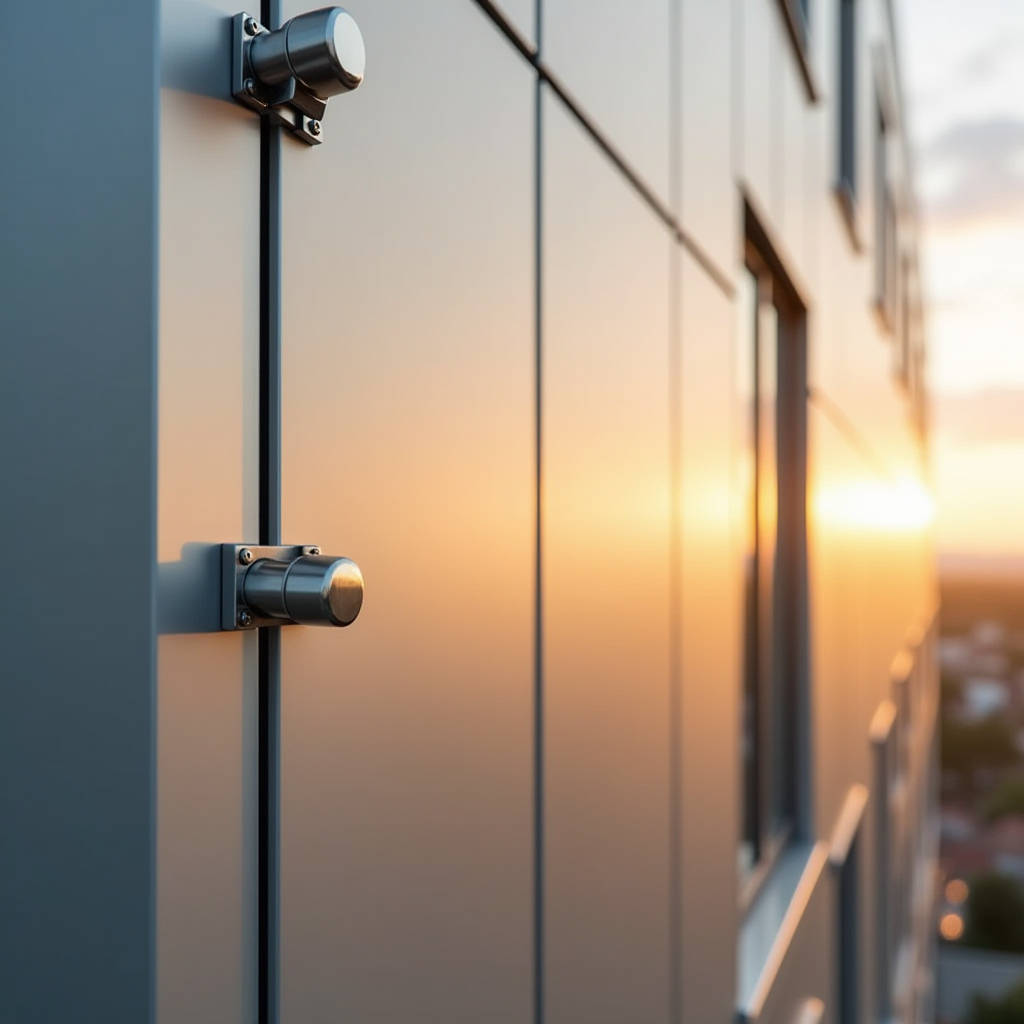
When a facade contractor looks at a rainscreen specification and sees "visible fixing," the first question is rarely about aesthetics. It is about load path. A Visible Fixing Aluminum Clip does more than hold a panel in place — it transfers wind suction, dead load, and thermal movement from the cladding into the substructure, all while sitting exposed to decades of UV, rain, and airborne chlorides. The mechanical simplicity of an exposed clip system is deceptive. Behind every stainless steel or aluminum clip fastened to a solid aluminium panel is a chain of engineering decisions: alloy selection, screw embedment depth, bearing surface area, and the fatigue behavior of the fastener under cyclic loading. Get one link wrong, and the entire facade becomes a liability. This article examines the engineering logic behind visible clip systems for solid aluminium cladding panels, focusing on how clip geometry, material pairing, and installation tolerances directly determine the long-term performance of a ventilated rainscreen.
What a Visible Fixing Aluminum Clip Actually Does
At its core, a Visible Fixing Aluminum Clip is a discrete mechanical fastener that secures a solid aluminium panel to a vertical or horizontal subframe. Unlike concealed systems that rely on adhesive bonding, kerf cuts, or rear-panel anchors hidden inside the cavity, the visible clip grips the panel edge or face and remains exposed on the finished facade surface. The exposed nature of the clip is not a design compromise — it is a deliberate engineering choice that prioritizes mechanical interlock, ease of inspection, and the ability to replace individual panels without dismantling adjacent units.
The clip performs three structural functions simultaneously. First, it resists positive and negative wind pressure by transferring suction loads from the panel face into the aluminium extrusion or steel bracket behind it. Second, it carries the dead weight of the panel — and for a 3.0mm solid aluminium sheet measuring 1.2 meters by 3.0 meters, that is roughly 29 kilograms — down through the subframe to the building structure. Third, it accommodates differential thermal expansion between the aluminium panel and the supporting frame. A 3-meter-long aluminium panel subjected to a 60°C temperature swing will expand by approximately 4.2mm. The clip must allow this movement without binding, buckling, or transmitting stress into the panel corners where fatigue cracks initiate.
Material Selection: Stainless Steel vs. Aluminum Clips
The choice between stainless steel and aluminum for the clip body is not trivial. Each material introduces a distinct set of galvanic, mechanical, and fabrication trade-offs that ripple through the entire facade design.
Stainless steel clips, typically grade 304 or 316, offer high tensile strength — commonly 500-700 MPa for cold-worked components — and excellent resistance to stress corrosion cracking. A 316 stainless clip in a coastal environment with high chloride deposition will outlast an aluminium clip of equivalent cross-section by a factor of three to five. However, stainless steel in direct contact with aluminium creates a galvanic couple. The aluminium panel becomes the anode and corrodes sacrificially. The standard mitigation is a physical separator: a 0.5mm to 1.0mm EPDM or nylon gasket placed between the clip jaw and the panel edge. Without this isolator, pitting corrosion can appear on the panel surface within 18 to 24 months in marine exposure zones.
Aluminum clips, extruded from 6063-T6 or 6061-T6 alloys, eliminate the galvanic mismatch. They share the same electrochemical potential as the panel, so no isolation gasket is required. The trade-off is strength. A 6063-T6 extrusion has a yield strength of approximately 170 MPa, roughly one-third that of cold-formed 316 stainless. To compensate, the clip cross-section must be larger, which increases the visible footprint on the facade. For architects who want the clip to read as a deliberate shadow line, this can be acceptable. For those seeking minimal visual intrusion, the bulkier aluminum clip becomes a design problem.
| Property | 316 Stainless Steel Clip | 6063-T6 Aluminum Clip |
|---|---|---|
| Tensile Yield Strength | 500-700 MPa (cold-worked) | 170-215 MPa |
| Galvanic Compatibility with Al Panel | Requires EPDM/nylon isolator | Compatible, no isolator needed |
| Corrosion Resistance (Marine) | Excellent (316 grade) | Moderate; requires anodizing or PVDF |
| Thermal Expansion Coefficient | 16.0 × 10⁻⁶ /°C | 23.4 × 10⁻⁶ /°C |
| Visible Footprint | Smaller, compact profile | Larger cross-section for equivalent strength |
| Typical Cost Ratio (per clip) | 1.0 (baseline) | 0.6-0.8 |
| On-Site Adjustability | Limited; harder to field-modify | Easier to cut, drill, or shim |
Clip Geometry and Load Distribution
The shape of a Visible Fixing Aluminum Clip dictates how loads travel from the panel into the substructure. The most common geometries — L-shaped retention brackets, T-shaped support clips, and U-shaped grip profiles — each distribute stress differently across the panel edge.
An L-shaped clip bears on the panel face or edge and transfers load through a single screw into the vertical profile. The load path is short and direct, but the single-point connection concentrates bending stress at the screw shank. Under cyclic wind loading, the screw hole in the aluminum profile can elongate, producing a condition known as "slot wear." Once the hole elongates by more than 0.3mm, the panel begins to rattle, and the clip loses preload. T-shaped clips spread the bearing load across two screw points, halving the stress on each fastener. This geometry is preferred for panels above 2.5mm thickness in high-wind zones where design wind pressures exceed 2.0 kPa.
U-shaped grip clips engage the panel edge on both the front and rear faces, creating a clamping action. The friction generated between the clip jaw and the panel surface contributes to load transfer, reducing the reliance on the screw alone. For solid aluminium panels with a PVDF coating, the clamping force must be controlled to avoid cracking the coating at the grip line. A maximum clamping pressure of 8-12 N/mm² is typical for 2.5mm and 3.0mm panels with a 35-40 micron PVDF finish.
Wind Load: The Numbers That Drive Clip Spacing
Clip spacing is not an architectural decision. It is a structural calculation that begins with the design wind pressure for the project location. A building in Miami (ASCE 7-22, Risk Category II, Exposure C) might see design wind pressures of 2.4 kPa at the corner zones. The same building in an inland European city designed to EN 1991-1-4 might see 1.1 kPa.
For a solid aluminium panel measuring 1,500mm × 1,000mm × 3.0mm, the total wind load area is 1.5 m². At 2.4 kPa, the panel experiences 3,600 N of suction force. If four clips secure the panel perimeter, each clip carries 900 N in tension. A properly specified 316 stainless clip with a 4.8mm screw into a 3mm-thick aluminium profile can typically handle 1,200-1,500 N in pull-out, giving a safety factor of 1.3 to 1.6. Drop to three clips, and the per-clip load jumps to 1,200 N, eating into the safety margin. This is why corner zones — where wind suction peaks — almost always require reduced clip spacing or additional intermediate clips.
The American Architectural Manufacturers Association (AAMA) provides testing protocols under AAMA 501.1 for dynamic wind load resistance that are directly applicable to visible clip systems. Similarly, the ISO 12567 standard governs thermal performance testing of curtain wall systems, which is relevant when clip thermal bridges are evaluated.
Thermal Bridging and Condensation Risk
A Visible Fixing Aluminum Clip that penetrates the insulation layer creates a point thermal bridge. Aluminum has a thermal conductivity of approximately 160 W/m·K, and stainless steel around 15 W/m·K. When a clip connects the cold exterior panel to the warm interior subframe, heat conducts through the clip body, lowering the internal surface temperature at the clip location.
In cold climates, this local temperature drop can push the interior surface below the dew point, resulting in condensation on the inside face of the subframe. Over multiple heating seasons, this moisture can corrode the back side of the clip and the subframe connection. The standard countermeasure is a thermal break pad — typically a 2mm to 4mm thick PVC or nylon isolator — placed between the clip and the vertical profile. This reduces the point thermal transmittance (χ-value) of the connection. For a typical stainless clip without a thermal break, the χ-value might be 0.08 W/K. With a 4mm nylon isolator, it drops to approximately 0.02 W/K, a fourfold reduction.
Specifiers working on projects that must meet ISO 10211 thermal bridge calculation requirements should request χ-values from the clip manufacturer. If the manufacturer cannot provide them, a conservative assumption of 0.10 W/K per clip is a safe starting point for energy modeling.
Installation Tolerances and On-Site Reality
The best-engineered clip is worthless if the substructure is out of plane. A Visible Fixing Aluminum Clip system typically demands a substrate flatness of ±2mm over a 2-meter straight edge. In practice, concrete slabs and blockwork walls rarely meet this tolerance without correction. The subframe installer must use adjustable brackets or shims to bring the vertical profiles into plane before the cladding panels arrive on site.
Panel edge preparation is equally critical. Solid aluminium panels arrive from the fabricator with pre-drilled or pre-routed clip engagement slots. If the slot position is off by even 1.5mm relative to the clip location on the subframe, the installer faces a choice: force the panel into position, which preloads the clip and risks fatigue cracking, or re-drill the slot on site, which compromises the PVDF edge seal and voids the coating warranty. The solution is a coordinated digital workflow: the clip layout must be defined in the same 3D model used to generate the panel fabrication drawings. Panel supplier Futeng® addresses this by providing clip-location data directly from the panel shop drawings, ensuring that the fabricator and the installer work from the same reference points.
Corrosion: The Silent Failure Mode
Visible clips live on the outside of the building. They are washed by rain, baked by sun, and in coastal or industrial environments, exposed to chloride or sulfur dioxide deposition. The failure mode that concerns facade engineers most is not general corrosion — which is visible and slow — but crevice corrosion at the screw-to-clip interface.
When a stainless steel screw is driven into a stainless clip, the threads create microscopic crevices where oxygen-depleted zones form. In the presence of chloride ions, these crevices become anodic sites, and corrosion initiates inside the thread engagement, invisible from the outside. After 5 to 8 years in a marine environment, the screw head can snap off under wind load with no prior visual warning. The prevention is straightforward: specify 316 stainless for both clip and screw in any location within 5 kilometers of saltwater, and apply a thread-locking compound that also acts as a crevice sealer. For inland projects, 304 stainless is generally adequate, though industrial zones with SO₂ emissions warrant the same 316 upgrade.
The ASTM B117 salt spray test is the standard accelerated corrosion test for clip assemblies. A minimum of 1,000 hours with no red rust on 316 stainless components is a reasonable specification benchmark. For aluminum clips, ASTM B244 governs anodizing thickness, and a Class I anodized finish (minimum 18 microns) is recommended for exterior exposure.
Panel Thickness and Clip Compatibility
Not every visible clip works with every panel thickness. A clip designed for 6mm fiber cement or 8mm HPL panels will not grip a 2.0mm solid aluminium sheet securely. The clip jaw opening must match the panel thickness plus the coating thickness, with a tolerance band of approximately ±0.3mm for a reliable friction grip.
For 2.0mm solid aluminium panels, the clip jaw typically has an opening of 2.2mm to 2.5mm, allowing for the 35-40 micron PVDF coating on both faces. For 2.5mm panels, the jaw opens to 2.7mm to 3.0mm. For 3.0mm panels, the jaw opens to 3.2mm to 3.5mm. Using a clip with a jaw that is too wide results in panel movement and impact noise during wind gusts. Too narrow, and the installer will struggle to engage the panel, potentially bending the clip or scratching the coating.
"The clip is not a commodity item. It is a precision component whose geometry must match the specific panel thickness, coating system, and design wind load of the project. Substituting a generic clip because it looks similar is the fastest route to a facade failure."
Acoustic Performance Under Wind and Rain
A facade that rattles during a storm erodes occupant confidence, even if it is structurally safe. Visible clip systems can generate noise through two mechanisms: panel-to-clip impact when wind gusts cause the panel to lift and slap back against the clip jaw, and clip-to-subframe vibration transmitted through the screw connection.
The first mechanism is controlled by ensuring adequate clip preload and minimizing the clearance between the clip jaw and the panel. A clearance of 0.1mm to 0.2mm is tight enough to prevent rattling while still allowing thermal expansion. The second mechanism is addressed by inserting a thin EPDM washer between the clip body and the aluminium profile, which damps high-frequency vibration transmission. Testing per ISO 10140 can quantify the sound reduction index of the complete facade assembly, though in practice, most projects rely on the absence of occupant complaints rather than formal acoustic testing for the clip system specifically.
Fire Performance Considerations
Visible clips are small components, but they sit inside the ventilated cavity of a rainscreen — the same cavity that can act as a chimney in a fire. If the clip material melts or loses strength at elevated temperatures, panels can detach and fall, creating a hazard for firefighters and evacuation routes below.
Aluminum clips lose approximately 50% of their yield strength at 200°C and essentially all structural capacity by 400°C. Stainless steel clips retain over 70% of their room-temperature strength at 500°C and remain structurally viable above 700°C. For buildings over 18 meters in many jurisdictions, the use of non-combustible materials in the rainscreen cavity is mandatory. Stainless steel clips satisfy this requirement without qualification. Aluminum clips can also comply, but the specifier must verify that the clip alloy and geometry maintain adequate strength at the design fire temperature, which typically requires project-specific engineering judgment.
Cost Drivers Beyond the Unit Price
The purchase price of a Visible Fixing Aluminum Clip — typically $0.80 to $4.50 per unit depending on material, geometry, and finish — is a small fraction of the total installed facade cost. But the clip drives costs elsewhere. A clip that requires an EPDM isolation gasket adds material and labor. A clip that demands tighter substructure tolerances increases the cost of the support framing. A clip that cannot be adjusted on site forces the installer to rework panels, which adds labor hours and waste.
The total cost of ownership for a visible clip system should account for: the clip unit cost, the cost of any required isolators or thermal breaks, the additional subframe cost to achieve the required flatness tolerance, the labor cost per clip for installation (typically 2-4 minutes per clip for an experienced crew), and the long-term maintenance cost associated with clip inspection and potential replacement over a 30-year service life. When these factors are summed, a $2.00 clip with a simple installation sequence often delivers a lower total installed cost than a $1.20 clip that requires shimming, isolator placement, and post-installation adjustment.
Specifying a Visible Clip System: A Practical Checklist
Writing a specification for a visible clip rainscreen requires more than referencing a product data sheet. The following checklist addresses the engineering parameters that determine whether the system will perform over the building's service life:
- Clip material and grade: Specify 316 stainless for marine/coastal, 304 for inland, or 6063-T6 aluminum with Class I anodizing for galvanic compatibility.
- Clip geometry: Define jaw opening to match panel thickness plus coating, with tolerance ±0.3mm.
- Fastener specification: Screw material, diameter, and embedment depth into the subframe. Minimum 4.8mm diameter for structural connections.
- Galvanic isolation: Require EPDM or nylon separator if stainless clip contacts aluminum panel directly.
- Thermal break: Specify thermal isolator pad for clips that penetrate the insulation layer in cold climates.
- Clip spacing: Calculated per project wind loads, with reduced spacing in corner zones per ASCE 7 or EN 1991-1-4.
- Substrate tolerance: ±2mm over 2 meters for the subframe plane. Verify with site measurements before panel installation.
- Corrosion testing: Minimum 1,000 hours ASTM B117 for stainless assemblies; ASTM B244 Class I for anodized aluminum.
- Fire rating: Confirm clip material meets non-combustibility requirements for the building height and jurisdiction.
- Replaceability: Verify that individual panels can be removed and reinstalled without damaging adjacent panels or clips.
The Visible Fixing Aluminum Clip is a small component that carries an outsized responsibility. It connects the aesthetic surface of the building to the structural backbone behind it. When the engineering is right — material matched to environment, geometry matched to panel thickness, spacing matched to wind load — the system delivers decades of reliable service with minimal maintenance. When it is wrong, the failure is visible, expensive, and dangerous. The difference between the two outcomes is not luck. It is specification discipline, informed by the numbers that matter.