Concealed Fixing Aluminum Bracket Engineering Load Paths and Installation Specs for Solid Aluminium Facades
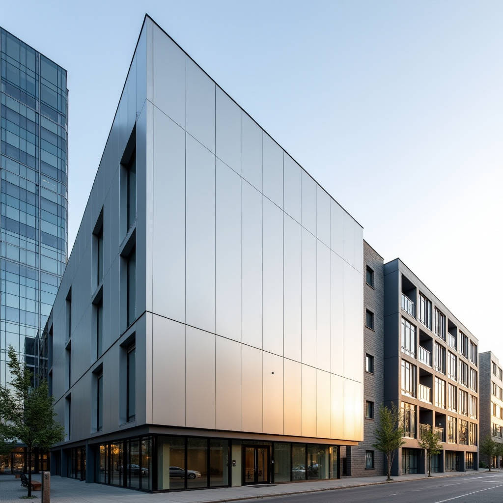
Architects and facade engineers chasing a perfectly flush building envelope keep running into the same problem: visible fasteners. Exposed rivets, screw heads, and bracket edges break the clean visual plane that solid aluminium cladding is supposed to deliver. The Concealed Fixing Aluminum Bracket solves this by shifting all mechanical connections behind the panel face, leaving nothing but uninterrupted metal on the exterior. This is not a cosmetic gimmick. Moving fasteners out of sight changes how the entire rainscreen performs under wind load, thermal cycling, and moisture exposure. Getting the bracket design right, from alloy selection to the specific anchoring geometry, determines whether a facade stays flat and silent for 20 years or starts rattling in the first storm season. Here is a ground-level look at how these brackets work, where they fail, and what to specify before a single panel goes up on site.
What a Concealed Fixing Aluminum Bracket Actually Does
A concealed fixing bracket performs three jobs simultaneously. It carries the dead load of the solid aluminium panel, transfers wind pressure and suction to the structural backup wall, and accommodates thermal movement without binding. The bracket sits entirely behind the panel, typically engaging with a factory-installed rear clip, a routed edge channel, or a folded return leg on the panel perimeter. Once the panel snaps or slides into place, no hardware remains visible from the exterior.
The load path matters. A properly engineered concealed bracket routes forces through the bracket body into the vertical rail or horizontal girt system, then into the primary structure. The bracket itself is usually extruded from 6063-T6 or 6061-T6 aluminium alloy, chosen for its balance of strength, extrudability, and corrosion resistance. Wall thickness on the bracket body typically runs 2.5 mm to 4.0 mm, depending on the panel size and wind zone. Undersized brackets are a common failure point. When a 3.0 mm thick solid aluminium panel weighing 8 to 10 kg per square meter gets hit by a 2.5 kPa wind gust, the bracket sees both bending and shear. If the bracket leg is too thin, it yields at the anchor point and the panel shifts, sometimes permanently.
Panel Compatibility and Material Constraints
Not every aluminium panel works with concealed fixing. The system requires a panel that can hold its shape without mid-span support and has enough edge stiffness to engage the bracket without deforming. Solid aluminium sheets at 2.0 mm, 2.5 mm, and 3.0 mm thickness are the standard candidates. Thinner material, like 1.5 mm, tends to oil-can under thermal stress and can pull away from the bracket engagement slot over time.
PVDF-coated panels add another layer of consideration. The coating thickness, typically 25 to 35 microns for a two-coat system and 40 to 50 microns for a three-coat system, does not affect bracket engagement directly. But the coating on the panel's rear return leg, where the bracket grips, needs to be intact. Any scratch through the PVDF layer at the grip point becomes a corrosion initiation site. Specifiers should require that brackets include a nylon or EPDM isolator pad at every contact point. This prevents galvanic corrosion between the bracket and the panel, even when both are aluminium, because the alloys can differ enough to create a potential difference in the presence of moisture.
Bracket Geometry and the Four Main Types
Concealed fixing brackets for solid aluminium cladding fall into four broad categories, each suited to a different facade condition.
1. Rear-Clip Brackets
These are the most common in rainscreen applications. A male clip, factory-bonded or mechanically fastened to the rear of the panel, engages a female receiver on the bracket. The panel hangs on the bracket and is locked in place with a set screw or a spring-loaded retainer. Rear-clip systems allow for panel removal from the outside, which matters for maintenance access behind the cladding. The clip adhesive must be structural-grade, typically a two-part epoxy or a high-performance acrylic tape with a minimum shear strength of 1.0 MPa after full cure.
2. Edge-Rout Brackets
Here, a groove is CNC-routed into the panel edge, and the bracket tongue slides into that groove. The bracket is completely hidden within the panel thickness. Edge-rout systems work best with 3.0 mm solid aluminium, where enough material remains above and below the groove to resist splitting. The rout depth is usually 12 mm to 15 mm, leaving a 6 mm to 8 mm material bridge. Tolerances are tight: the groove width must match the bracket tongue thickness with no more than 0.3 mm of play, or the panel will rattle.
3. Folded-Return Brackets
For panels with a folded return leg on the top and bottom edges, the bracket hooks over the return. This is a simple, robust method that does not require secondary clips or adhesives. The downside is that the return leg is visible from below if the soffit is open, so this method is typically used where the panel bottom edge is shielded by a horizontal shadow gap or another panel.
4. Toggle-and-Cam Brackets
A rotating cam mechanism on the bracket engages a slot on the panel rear. Turning the cam with a hex key from the panel edge locks the panel in place. This system allows fine adjustment of panel plane and is popular on high-end commercial projects where panel alignment tolerances are specified at ±1.5 mm across a 20-meter facade run. The cam mechanism adds cost but reduces installation time because no secondary locking step is needed.
Wind Load Performance and Structural Considerations
Wind load is the governing case for concealed bracket design. A standard calculation for a 1,200 mm by 2,400 mm solid aluminium panel in a suburban exposure at 30 meters building height might look like this:
The design wind pressure, based on ASCE 7-22 or EN 1991-1-4, could be 1.8 kPa for serviceability and 2.7 kPa for ultimate limit state. The panel area is 2.88 m², so the total wind force per panel at ultimate is roughly 7.8 kN. This force is distributed across the number of brackets per panel, typically four to six depending on the panel aspect ratio. Each bracket must resist approximately 1.3 kN to 1.95 kN in pull-out and a similar magnitude in shear.
Bracket pull-out capacity from the subframe depends on the fastener type and the subframe material. An M6 stainless steel screw into a 3.0 mm thick aluminium vertical rail might yield 2.5 kN to 3.0 kN in pull-out, giving a safety factor of around 1.5 to 2.0. But that same screw into a thin steel stud might only give 1.0 kN, which is marginal. The bracket must be specified alongside the subframe, not in isolation.
Thermal movement is the other structural variable. A 3-meter-long aluminium panel subjected to a 60°C temperature swing expands by approximately 4.2 mm (using a coefficient of 23 × 10⁻⁶ /°C). The bracket system must allow this movement without binding. Fixed-point brackets are used at one location per panel, typically the center, and sliding-point brackets are used at all other locations. The sliding brackets include an elongated hole or a slotted connection that permits longitudinal movement. If the installer mistakenly fixes all brackets rigidly, the panel will buckle on a hot day or pull the fasteners loose on a cold one.
Corrosion Protection and Material Pairing
Aluminium brackets in a concealed fixing system live in a harsh microclimate. The cavity behind the cladding panel sees condensation cycles, especially in climates with cold nights and warm, humid days. Bracket corrosion can go unnoticed for years because the damage is hidden, until a panel comes loose.
The baseline specification is 6063-T6 aluminium with a Class I anodized finish to AA-M12C22A31, minimum 15 microns thickness. For coastal or industrial environments, a 5% magnesium 5083 alloy bracket with a marine-grade anodized finish is a better choice. Stainless steel brackets, grade 316, are an option but introduce a galvanic couple with the aluminium panel that must be managed with isolation pads.
Fasteners deserve equal attention. A2-70 (304) stainless steel screws are the minimum. Within 5 km of a coastline, A4-80 (316) stainless steel is required. The screw heads should be isolated from the aluminium bracket with a nylon washer to prevent crevice corrosion at the interface.
| Bracket Material | Finish | Corrosion Resistance | Recommended Environment | Typical Cost Index (per bracket) |
|---|---|---|---|---|
| 6063-T6 Aluminium | Anodized 15μm AA-M12C22A31 | Moderate | Urban, inland | 1.0 |
| 6063-T6 Aluminium | PVDF Coated 40μm | Good | Urban, light industrial | 1.3 |
| 5083 Aluminium | Marine-grade Anodized 20μm | Very Good | Coastal (>5 km) | 1.7 |
| 316 Stainless Steel | Passivated | Excellent | Coastal (<1 km), heavy industrial | 2.5 |
| 6061-T6 Aluminium | Bare (mill finish) | Poor | Interior only | 0.7 |
Installation Sequence and Common Field Errors
The best bracket design fails if the installation sequence is wrong. The correct order for a concealed fixing rainscreen is: install subframe rails, set bracket positions with a laser, fix brackets to rails, hang panels, adjust, and lock. What often happens on site is that the subframe is out of plane by 5 mm to 10 mm, and the installer compensates by shimming brackets or over-tightening fasteners. This preloads the bracket and reduces its fatigue life.
Another recurring problem is bracket spacing. The maximum bracket spacing is determined by the panel stiffness and the wind load, but a rule of thumb for 3.0 mm solid aluminium is 600 mm centers along the panel perimeter and 900 mm centers for intermediate brackets. Exceeding these distances leads to visible panel deflection between supports, particularly under negative wind pressure where the panel is being sucked outward.
Panel-to-panel joints also interact with bracket placement. The joint width, typically 10 mm to 20 mm, is maintained by the bracket positioning. If brackets are installed even 2 mm out of position, the joint width varies visibly across the facade. On a project with 500 panels, a consistent 2 mm error creates a cumulative visual defect that is obvious from street level.
Fire Safety and Cavity Considerations
Concealed fixing brackets sit inside the ventilated cavity behind the cladding. In a fire, this cavity can act as a chimney, drawing flames upward. The bracket material must not contribute to fire spread. Aluminium brackets melt at approximately 650°C, which is well above the temperature at which cavity barriers should have activated. The key fire safety requirement is that the bracket does not fail before the cavity barriers close off the ventilation path.
For buildings over 18 meters, many jurisdictions require non-combustible materials throughout the rainscreen assembly. Solid aluminium panels and aluminium brackets meet this requirement. The bracket's EPDM or nylon isolator pads are typically small enough to fall below the threshold for combustible content in the cavity. Specifiers should verify that the total combustible material in the cavity, including brackets, insulation, and vapor barriers, stays within the limits set by the local building code, such as the 0.5 MJ/kg limit referenced in some European standards.
Cost Breakdown and Value Engineering
Concealed fixing systems cost more than face-fixed alternatives, but the premium is not as large as many assume once the full picture is considered. A face-fixed system requires stainless steel screws with color-matched heads, which are expensive, and the installation labor includes drilling and fastening each screw from the exterior. A concealed system eliminates exterior fasteners and the associated drilling, but adds the cost of the brackets themselves and the factory-applied rear clips or edge routing.
A rough cost comparison for a 1,000 m² facade area:
- Face-fixed system: 4 fasteners per panel, 500 panels, 2,000 fasteners at approximately $0.80 each, plus installation labor at 0.25 hours per panel. Total material and labor for fixing: roughly $8,000 to $12,000.
- Concealed fixing system: 6 brackets per panel, 500 panels, 3,000 brackets at approximately $3.50 to $6.00 each depending on type, plus factory clip bonding at $2.00 per clip. Total bracket and clip cost: $16,500 to $24,000. Installation labor is lower, around 0.15 hours per panel, because the panel simply hangs on the brackets. Total installed cost: $22,000 to $32,000.
The concealed system costs roughly 2.5 to 3 times more for the fixing hardware, but the installed cost difference narrows to about 1.8 to 2.2 times because of labor savings. For projects where the architectural brief demands a clean facade without visible fasteners, this premium is absorbed into the overall cladding budget without breaking it.
Suppliers like Futeng® offer solid aluminium cladding panels with factory-prepared rear clip systems, which can reduce the on-site labor component further because the panel arrives ready to hang. This shifts quality control from the scaffold to the factory floor, where bonding conditions are controlled and consistent.
Specification Checklist for Engineers
Writing a tight specification for concealed fixing aluminium brackets prevents substitution of inferior hardware. The following points should be covered in the project spec:
- Alloy and temper: Specify 6063-T6 or 6061-T6 for inland; 5083-H116 for marine. Do not accept unspecified "aluminium alloy."
- Bracket wall thickness: Minimum 3.0 mm for load-bearing legs. Verify with shop drawings.
- Finish: Anodized per AA-M12C22A31, Class I, 15 μm minimum. For coastal, increase to 20 μm or switch to PVDF coating.
- Isolator pads: EPDM or nylon, 1.0 mm minimum thickness, at all panel-to-bracket and bracket-to-rail contact points.
- Fasteners: Stainless steel A2-70 minimum. A4-80 within 5 km of salt water. Include nylon washers under screw heads.
- Pull-out capacity: Each bracket must demonstrate a minimum pull-out capacity of 2.0 kN from the specified subframe, verified by on-site pull-out testing on a minimum of 5% of brackets.
- Thermal movement: System design must accommodate a minimum of ±3 mm panel movement per meter of panel length. Sliding connections must be clearly identified on shop drawings.
- Fire performance: Bracket material to be classified as A1 or A2-s1,d0 per EN 13501-1 or equivalent.
- Mock-up testing: A full-scale mock-up of not less than 3 panels wide by 3 panels high, using the actual bracket system, to be erected and inspected before main facade work begins.
Testing and Quality Assurance
On-site testing of concealed fixing brackets is not optional. The two most important tests are pull-out testing and cyclic wind load testing.
Pull-out testing uses a hydraulic tester to apply a tensile load to individual brackets until failure or until 150% of the design load is reached. The test is done after the brackets are installed on the actual subframe, using the same fasteners and installation method. A minimum of 5% of brackets should be tested, with a higher percentage in the corners and perimeter zones where wind loads are highest.
Cyclic wind load testing is done on a mock-up, not on the building. A pressure chamber applies positive and negative pressure cycles that simulate the design wind load for the project location. The test protocol typically follows ASTM E330 or AAMA 501.1, with 50 cycles at service load and 5 cycles at 150% of design load. After cycling, the mock-up is inspected for permanent deformation, fastener loosening, and bracket cracking.
For projects following European standards, the relevant test method is CWCT (Centre for Window and Cladding Technology) Section 5, which covers both static and cyclic pressure testing of rainscreen systems. The CWCT standard also requires a hose test for water penetration, where water is sprayed at the mock-up at a rate of 3.4 liters per minute per square meter while a negative pressure differential is maintained. The concealed fixing system must not allow water to reach the inner face of the cavity.
Supply Chain and Lead Time Realities
Concealed fixing brackets are not off-the-shelf items for most solid aluminium cladding projects. They are typically custom-extruded to match the specific panel system. The extrusion die for a custom bracket profile costs $1,500 to $3,000 and takes 3 to 4 weeks to produce. After die approval, extrusion production runs 2 to 3 weeks, followed by anodizing or coating at 1 to 2 weeks. Total lead time from bracket design approval to delivery is 8 to 12 weeks.
This lead time must be factored into the project schedule. Ordering brackets too late is a common reason for facade delays. The bracket design should be finalized at the same time as the panel shop drawings, not after. A practical approach is to include bracket samples in the pre-construction submittal package so that approval happens before the bulk order is placed.
Minimum order quantities for custom extrusions are typically 500 kg to 1,000 kg of billet, which translates to roughly 2,000 to 5,000 brackets depending on the profile size. For smaller projects, using a standard bracket profile from a system supplier can reduce lead time and avoid the die charge, but the panel geometry must be designed around the available bracket, not the other way around.
When Concealed Fixing Is Not the Right Answer
There are projects where concealed fixing creates more problems than it solves. If the facade design includes a lot of small, irregularly shaped panels, the bracket count per panel increases and the cost per square meter escalates. If the building is in a high-seismic zone, the rigid connection of a concealed bracket may not provide enough drift capacity, and a face-fixed system with oversized holes for movement might be safer.
Renovation projects where the existing substrate is uneven also pose challenges. A concealed fixing system requires a subframe that is flat within ±3 mm over any 3-meter length. If the existing wall is masonry with 20 mm of undulation, the cost of leveling the substrate can exceed the cost of the entire bracket system. In these cases, an adjustable face-fixed system may be the more practical, if less elegant, solution.
The decision to use concealed fixing should be driven by the architectural intent and the site conditions, not by a blanket preference for hidden hardware. A well-executed face-fixed facade with thoughtfully detailed fastener patterns can look intentional and disciplined. But when the design calls for a monolithic, uninterrupted metal surface, the Concealed Fixing Aluminum Bracket is the only way to get there. The engineering is straightforward, the failure modes are well understood, and the cost premium is manageable when planned from the start. What matters is that the bracket specification gets the same level of attention as the panel specification. Because a beautiful 3.0 mm PVDF-coated solid aluminium panel means nothing if it is hanging on a bracket that was an afterthought.