Aluminum Subframe System Engineering Load Paths Thermal Bridging and Site Installation
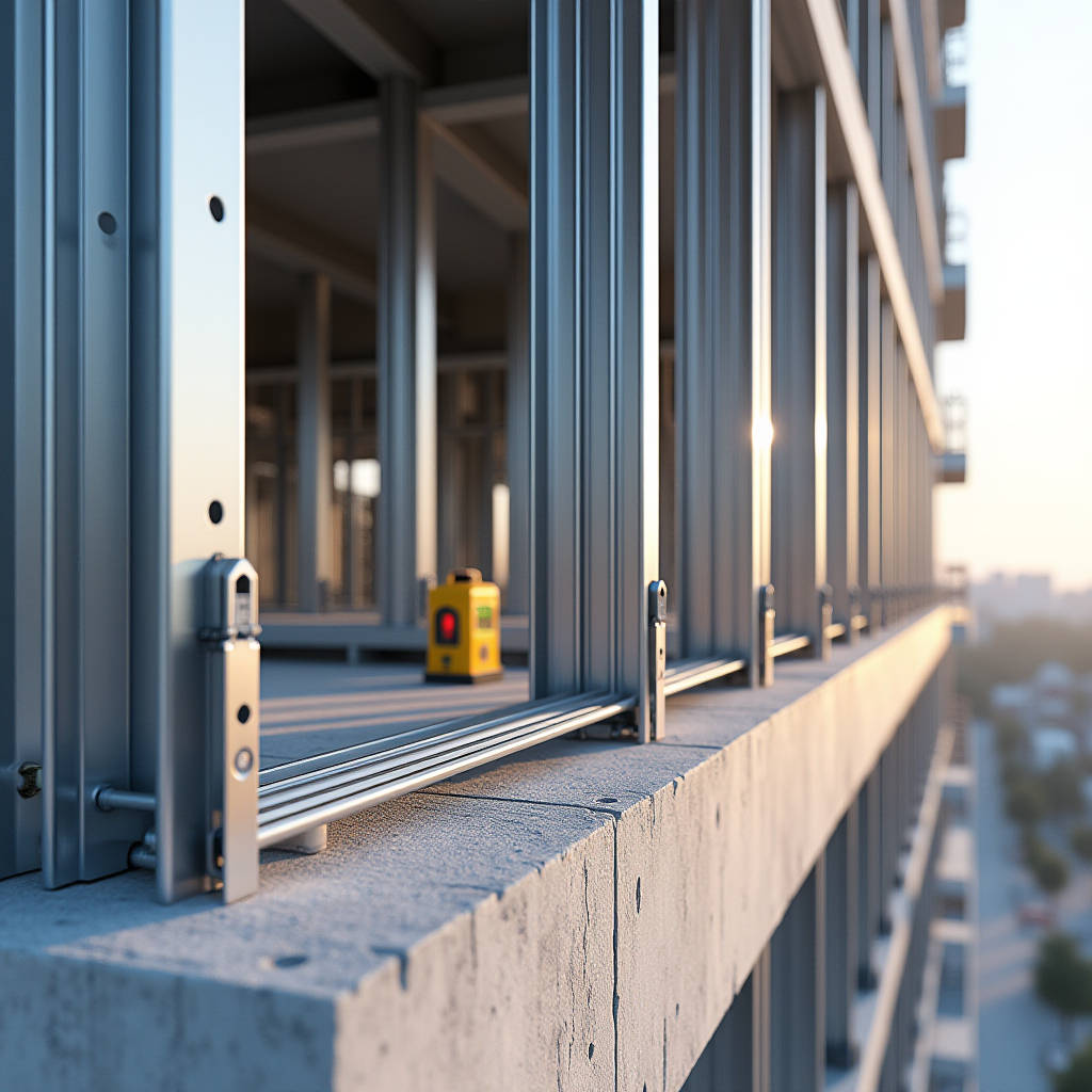
When a facade contractor receives shop drawings for a 25-story commercial tower, the first question rarely concerns the cladding panel itself. The panels are specified. The alloy, the finish, the thickness — those decisions were made months ago during design development. What keeps a project manager awake at night is the aluminum subframe system that sits between the building structure and those panels. This hidden framework determines whether the installation stays on schedule, whether thermal bridges compromise the envelope performance, and whether the dead load calculations hold up under real-world conditions. An aluminum subframe system is not a commodity bracket-and-rail assembly. It is a structural interface that must reconcile the architect's geometric ambitions with the engineer's load path requirements, all while accommodating thermal movement, wind deflection, and the cumulative tolerances of the primary structure. Getting it wrong means rework, liquidated damages, and warranty disputes. Getting it right means the panels hang plumb, the insulation layer stays continuous, and the rainscreen cavity performs exactly as the hygrothermal model predicted.
What an Aluminum Subframe System Actually Does
The term "subframe" invites misunderstanding. It suggests something secondary, almost incidental. In drained and back-ventilated rainscreen construction, the aluminum subframe system functions as the primary load-transfer mechanism between the cladding panels and the building's structural frame. It carries the self-weight of the panels — which for solid aluminium sheets at 2.5mm or 3.0mm thickness can reach 7 to 9 kg per square meter — and transfers wind loads, both positive and negative, back to the substrate through a series of engineered brackets and vertical or horizontal rail profiles.
The system typically comprises three distinct component groups. First, the bracket assembly, which anchors to the primary structure — concrete slab edges, steel studs, or masonry backup walls — using stainless steel fasteners selected for the substrate type. Second, the rail profiles, which span between brackets and create the mounting plane for the cladding panels. Third, the connection hardware — clips, rivets, or proprietary interlocking mechanisms — that secure the panels to the rails while permitting differential thermal movement between the aluminum components and the building structure.
This three-tier architecture is not arbitrary. It solves a fundamental problem in facade engineering: the primary structure is never perfectly flat, never perfectly plumb, and never dimensionally identical to the architectural model. The aluminum subframe system absorbs these deviations through adjustability built into the bracket design, typically offering 30mm to 80mm of adjustability in the horizontal plane and 20mm to 50mm in the vertical. Without this adjustment range, every millimeter of structural tolerance would telegraph through to the finished facade surface.
Thermal Performance and the Bracket Problem
Every bracket that penetrates the insulation layer creates a thermal bridge. The thermal conductivity of aluminum — approximately 160 W/mK for 6063-T6 alloy — means that a continuous metal path from the cold exterior to the warm interior structure will bleed heat from the building. In heating-dominated climates, this manifests as higher energy bills. In cooling-dominated climates, it means condensation risk on interior surfaces.
The industry has responded with thermally broken bracket designs. These incorporate a structural thermal break — typically a reinforced polyamide or fiberglass-reinforced nylon element — between the bracket base plate and the rail attachment point. The performance difference is measurable. A standard aluminum bracket without a thermal break might exhibit a point thermal transmittance (χ-value) of 0.3 to 0.8 W/K, depending on geometry. A thermally broken bracket from a properly engineered aluminum subframe system can reduce that to 0.08 to 0.15 W/K. Across a facade with brackets spaced at 600mm centers vertically and 1200mm horizontally, the aggregate heat loss through hundreds of bracket penetrations becomes significant enough to affect whole-building energy modeling results.
This is not a theoretical concern. Projects pursuing Passive House certification or compliance with increasingly stringent energy codes — such as ASHRAE 90.1-2022 or the UK Building Regulations Part L — must account for every point thermal bridge in the envelope. Specifying an aluminum subframe system with verified thermal break performance, supported by third-party thermal modeling per ISO 10211, provides the documentation that energy consultants and building control officers require.
Adjustability, Tolerance, and the Reality of Site Conditions
Architectural drawings assume perfect geometry. Site conditions deliver something else. Concrete slabs cast with 10mm to 15mm of deviation from design position. Steel frames that deflect under construction loads. Substrate surfaces that vary by 5mm to 10mm over a 3-meter straightedge. The aluminum subframe system must reconcile these realities without compromising the finished facade plane.
Three-axis adjustability is the standard for serious rainscreen subframe platforms. The X-axis (horizontal, perpendicular to the rail direction) allows the bracket to accommodate substrate variation and set the cavity depth. The Y-axis (vertical, along the rail) permits the rail to slide within the bracket during installation, absorbing floor-to-floor height variations. The Z-axis (horizontal, along the rail direction) provides fine-tuning of panel joint alignment. Systems that offer only two-axis adjustment force the installer to compensate with shims, packers, or field modifications — all of which add labor hours and introduce quality control risks.
The bracket-to-rail connection deserves particular attention. Some systems use a simple bolted connection with slotted holes. More refined designs employ a serrated or toothed interface between bracket and rail that locks the position mechanically once the fastener is torqued. This prevents creep under cyclic wind loading — a phenomenon where a purely friction-based connection can gradually shift, causing panel misalignment that becomes visible months or years after handover.
Material Selection: Alloy, Coating, and Fastener Compatibility
Not all aluminum is equal in a subframe application. The dominant alloy for extruded subframe profiles is 6063-T6, which offers a good balance of extrudability, strength (minimum ultimate tensile strength of 215 MPa), and corrosion resistance. For brackets that carry higher loads — particularly at parapet conditions or around large openings where wind pressures are elevated — 6061-T6 may be specified for its higher strength (minimum UTS of 290 MPa).
Corrosion protection is a system-level consideration. The aluminum subframe system operates in the cavity behind the cladding, which is a ventilated but sheltered environment. In C2 and C3 corrosion categories per ISO 9223, mill-finish aluminum with a natural oxide layer is generally adequate. For C4 and C5 environments — coastal, industrial, or aggressive marine atmospheres — anodizing to AA20 or AA25 specification per AAMA 611 provides the necessary protection. Powder coating of subframe components is less common but may be specified where the cavity is visible through open joints or where the architect requires a consistent aesthetic behind perforated panels.
Galvanic corrosion is the hidden risk. Stainless steel fasteners (typically 304 or 316 grade) are standard for connecting aluminum subframe components. However, in marine environments, the combination of aluminum brackets and stainless steel fasteners in the presence of chloride-laden moisture can create a galvanic cell. The solution is isolating the dissimilar metals with nylon washers or specifying fasteners with appropriate coatings. This detail is often overlooked in generic specifications but becomes critical on waterfront projects.
Wind Load: From Code to Component Selection
Wind load governs the structural design of the aluminum subframe system. The starting point is the design wind pressure, calculated per the applicable code — ASCE 7-22 in the United States, EN 1991-1-4 in Europe, or AS/NZS 1170.2 in Australia and New Zealand. This pressure varies across the building elevation: highest at corners and edges, lower in the field areas, and amplified at parapets and roof edges.
A typical mid-rise building in Exposure Category B might see design wind pressures ranging from 1.0 kPa at the lower-floor field zones to 3.5 kPa or more at upper-floor corner zones. The aluminum subframe system must be engineered so that each component — bracket, rail, fastener, and clip — has sufficient capacity at the worst-case location. This is where value engineering becomes dangerous. Reducing bracket spacing from 600mm to 900mm centers might save 30% on bracket count, but if the rail span increases beyond the section's bending capacity under the design wind load, the rail will deflect excessively or fail.
Allowable deflection is a serviceability criterion separate from strength. Common practice limits rail deflection under design wind load to L/175 or L/240, where L is the span between brackets. For a 1200mm bracket spacing, L/175 permits 6.9mm of deflection. More than this, and the panel joints may open or close visibly, or the panels may contact the insulation layer, compressing it and reducing its thermal performance. Solid aluminium cladding panels at 2.5mm or 3.0mm thickness are relatively stiff, but they rely on the subframe for global support. A subframe that deflects excessively under wind will transfer bending stresses into the panel edges, potentially causing localized deformation or fastener fatigue over thousands of load cycles.
Fire Performance and the Non-Combustible Mandate
The regulatory trajectory is unambiguous. Following the Grenfell Tower tragedy and subsequent inquiries, jurisdictions worldwide have tightened requirements for facade materials. The aluminum subframe system, being entirely metallic, is inherently non-combustible and classified as A1 per EN 13501-1 or ASTM E136. This is a fundamental advantage over hybrid systems that incorporate polymer-based thermal breaks or composite rail materials.
However, the fire performance of the subframe cannot be considered in isolation. The complete wall assembly — including insulation, weather barriers, cavity closers, and fire stops — must be tested as a system. NFPA 285 is the standard test method for evaluating the fire propagation characteristics of exterior wall assemblies containing combustible components. An aluminum subframe system with thermally broken brackets may still form part of an NFPA 285-compliant assembly, provided the thermal break material is of limited quantity and the assembly design has been tested and certified. Specifiers should request the full assembly test report, not just a letter of compliance, and verify that the tested configuration matches the project's specific material stack-up.
Installation Sequence and the Labor Equation
The efficiency of an aluminum subframe system is measured in labor hours per square meter of facade. A well-designed system with intuitive bracket adjustment, captive fasteners, and pre-punched rail profiles can achieve installation rates of 15 to 25 square meters per installer per day for the subframe alone. A poorly designed system — with fiddly adjustments, loose fasteners, and excessive field drilling — might drop to 8 to 12 square meters per day.
The installation sequence follows a logical hierarchy. First, the bracket positions are surveyed and marked on the substrate, referencing the project's gridlines and datum levels. Laser levels are essential here; a 5mm error in bracket position at the base of the building becomes a 50mm error at the top if the deviation is systematic rather than random. Second, the brackets are fixed to the substrate, with the fastener type and embedment depth verified against the substrate material — wedge anchors for concrete, self-tapping screws for steel studs, and proprietary fixings for masonry. Third, the rails are hung on the brackets and adjusted to the correct plane. Fourth, the rails are locked in position, and the installed plane is checked with a taut wire or laser scan before any panels are mounted.
The most common installation error is failing to account for thermal movement. Aluminum expands and contracts at approximately 0.024mm per meter per degree Celsius. A 3-meter rail length subjected to a 60°C temperature swing — from -10°C on a winter night to 50°C on a summer afternoon with solar radiation — will experience 4.3mm of linear movement. If the rail is fixed rigidly at both ends, this movement will manifest as buckling or fastener distress. The aluminum subframe system must accommodate this movement through slotted connections, sliding joints, or expansion gaps detailed in the shop drawings. Installers who ignore these details and fix everything rigidly create problems that may not appear until the first seasonal temperature cycle.
Comparative Analysis of Subframe Configurations
The choice between vertical rail, horizontal rail, and grid-based subframe configurations has implications for structural performance, thermal bridging, and installation efficiency. The following table summarizes the key characteristics of each approach based on typical project data for solid aluminium cladding panel applications at 2.5mm to 3.0mm thickness.
| Configuration | Typical Rail Span | Bracket Density | Thermal Bridges | Installation Rate | Best Suited For |
|---|---|---|---|---|---|
| Vertical Rail (Primary) | 1200–1500mm | 0.7–1.0 per m² | Moderate | 18–25 m²/day | Floor-to-floor spans, tall narrow panels |
| Horizontal Rail (Primary) | 600–900mm | 1.2–1.8 per m² | Higher | 12–18 m²/day | Inter-story deflection accommodation |
| Grid System (Dual-Layer) | Variable | 1.5–2.5 per m² | Highest | 8–15 m²/day | Complex geometry, mixed panel sizes |
| Clip-On Cassette Rail | 800–1200mm | 0.8–1.2 per m² | Moderate | 20–28 m²/day | Repetitive panel modules, speed-critical |
The vertical rail configuration is the workhorse of commercial facade construction. It aligns with the natural load path — gravity runs vertically, and the rails carry panel self-weight directly to the brackets. Horizontal rail systems are often specified where the primary structure has significant inter-story deflection, as the horizontal orientation allows the rails to act as simply supported beams spanning between columns, isolating the cladding from structural movement. Grid systems add a second layer of rails, creating a framework that can support panels in multiple orientations, but at the cost of increased material, more thermal bridges, and longer installation time.
Procurement and Supply Chain Considerations
The aluminum subframe system represents 15% to 25% of the total facade material cost on a typical rainscreen project, but its impact on the critical path is disproportionate. Panels can be fabricated in parallel with other site activities. The subframe must be installed first, and until it is complete, no panels can be hung. Delays in subframe delivery translate directly into project delays.
Lead times for extruded aluminum subframe components typically range from 4 to 8 weeks, depending on the complexity of the profiles, the quantity, and the anodizing or finishing requirements. This is shorter than the 8 to 12 weeks typical for solid aluminium cladding panels with PVDF coating, but the subframe must be ordered early enough to arrive before the panels. A common procurement error is placing the panel order first and the subframe order later, resulting in panels sitting in storage while the site waits for brackets and rails.
For international projects, the logistics of shipping aluminum extrusions — long, relatively lightweight, and susceptible to damage if improperly packed — require careful planning. Suppliers with experience in export packaging, such as Futeng®, provide crating systems that protect the profiles during container transit and can be handled efficiently on site. The cost of replacing a bundle of rails that arrived bent or scratched far exceeds the incremental cost of proper packaging.
Quality Verification and On-Site Inspection
The installed aluminum subframe system should be inspected and documented before any panels are mounted. This is the last opportunity to correct alignment errors, missing fasteners, or inadequate bracket fixings without the cost of removing finished panels. A structured inspection protocol should verify bracket spacing against the approved shop drawings, torque values on all structural fasteners, the installed plane tolerance — typically ±3mm over a 3-meter straightedge — and the presence and correct installation of thermal break elements where specified.
Pull-out testing of bracket fixings is prudent on projects where the substrate condition is uncertain. A sample of fixings — typically 5 per substrate type, with a minimum of 3 — should be tested to verify that the actual pull-out capacity meets or exceeds the design value. This is particularly important on renovation projects where the existing substrate may be of unknown composition or condition. The cost of a day's pull-out testing is trivial compared to the cost of a bracket failure discovered after the cladding is installed.
Documentation matters. The inspection report, together with photographs of the installed subframe at each elevation and each floor level, forms part of the quality record that protects both the contractor and the specifier if questions arise later. On projects where the facade consultant or building control officer requires witness testing, having organized documentation accelerates the approval process.
Making the Right Specification Decision
Selecting an aluminum subframe system is not a matter of comparing bracket prices per piece. The total installed cost includes the subframe material, the labor to install it, the thermal impact on the building's energy performance, and the risk of future problems if the system is under-engineered for the project's specific conditions. A system that saves €5 per square meter on bracket cost but adds €15 per square meter in installation labor because of poor adjustability is a false economy. A system that eliminates thermal breaks to save cost but causes the building to fail its energy compliance check will cost far more in redesign and retrofit than was ever saved.
The most reliable approach is to engage with the subframe supplier during the design development phase, not during procurement. A supplier with engineering capability can review the project's wind loads, substrate conditions, and thermal requirements and propose a system configuration that is optimized for the specific project rather than a generic solution applied indiscriminately. This early engagement also allows the supplier to identify potential compatibility issues between the subframe and the specified cladding panels — clip geometry, joint dimensions, and attachment methods — before they become change orders.
The aluminum subframe system is the part of the facade that nobody sees but everybody relies on. When it works, the panels align perfectly, the joints stay consistent, and the building performs as designed. When it fails, the problems are visible, expensive, and public. The difference between these outcomes is determined by the engineering rigor applied to the subframe specification, not by the panels that hang on it.