Aluminum Facade Support System Load Path Engineering and Bracket Selection for Long Life Rainscreens
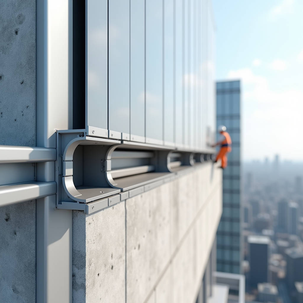
When a facade buckles under wind load or panels start rattling during a storm, the root cause almost never lies in the cladding material itself. It sits deeper, hidden behind the visible surface, in the Aluminum Facade Support System that holds everything together. The support framework is the skeleton that determines whether a building envelope performs for 30 years or starts failing in five. Yet procurement teams and even some specifiers treat it as an afterthought, focusing heavily on panel thickness and finish while leaving bracket selection, rail spacing, and thermal isolation to last-minute value engineering. This article examines the load-path mechanics, material compatibility, and installation sequencing that separate a durable aluminum rainscreen from one that generates callbacks. Every section draws from field observations across projects in Europe, the Middle East, and Southeast Asia, where humidity, wind, and seismic activity push these systems to their limits.
Why the Support System Dictates Facade Longevity
Solid aluminum cladding panels in 2.0mm, 2.5mm, or 3.0mm thicknesses are remarkably stiff for their weight. A 3.0mm PVDF-coated panel spanning 600mm between supports can handle substantial uniform pressure without permanent deformation. But that stiffness means nothing if the Aluminum Facade Support System transfers stress unevenly or allows differential movement to concentrate at fastener points.
The support system performs three distinct jobs simultaneously. First, it transfers wind suction and pressure from the panel face back to the primary structure. Second, it accommodates thermal expansion and contraction, which for aluminum can reach roughly 2.4mm per meter across a 100°C temperature swing. Third, it maintains the cavity ventilation path that makes rainscreen principles work. When any one of these functions gets compromised, the failure mode is predictable: oil-canning, fastener fatigue, or moisture entrapment behind the panels.
What complicates matters is that no single support configuration works universally. A 40-story tower in Dubai facing prevailing shamal winds needs different bracket spacing than a low-rise office in Rotterdam. The calculations shift again when the substrate changes from concrete to light-gauge steel framing. The AAMA 508 standard provides a baseline for structural performance testing, but the engineering judgment required to apply those numbers to a specific project remains substantial.
Load Path Engineering: Wind, Dead Load, and Seismic Considerations
Wind load drives most support system design decisions. The pressure distribution across a facade is never uniform. Corner zones experience suction forces 2 to 3 times higher than the field area, which means the Aluminum Facade Support System must be zoned accordingly. A common mistake is specifying the same bracket gauge and rail span across the entire elevation, which either over-engineers the field zones or under-engineers the corners.
Dead load calculations for solid aluminum cladding are straightforward. A 2.5mm panel weighs approximately 6.8 kg/m², and a 3.0mm panel comes in around 8.1 kg/m². The support system adds another 3 to 5 kg/m² depending on the rail profile and bracket density. These numbers are modest compared to stone or terracotta, but they accumulate on tall vertical spans. A 4-meter panel run supported only at top and bottom puts the full dead weight into shear on the lower brackets, and over time, creep can loosen connections if the bracket design lacks positive mechanical engagement.
Seismic design introduces a different set of requirements. The support system must allow inter-story drift without binding or fracturing. This typically means horizontal slotted connections at every other floor level and careful attention to the clearance between panel edges. In regions governed by ASCE 7 seismic provisions, the Aluminum Facade Support System needs to accommodate the calculated drift without panels contacting each other or transferring load into unintended paths.
Thermal Isolation: The Hidden Performance Gap
A continuous aluminum bracket running from the exterior rail through the insulation layer to the structural wall creates a thermal bridge that can slash the effective R-value of the wall assembly by 30% or more. The physics is unforgiving: aluminum conducts heat roughly 1,600 times more efficiently than mineral wool insulation. Every bracket that penetrates the insulation plane carries heat outward in winter and inward in summer.
Thermally broken brackets address this by inserting a low-conductivity material, typically reinforced polyamide or rigid PVC, between the interior and exterior halves of the bracket. The performance improvement is measurable. A standard aluminum L-bracket might have a thermal conductivity of 160 W/m·K, while a thermally broken equivalent drops to below 2.0 W/m·K through the isolator section. The trade-off is cost and complexity. Thermally broken brackets cost 40-60% more than standard brackets, and the isolator material must maintain its mechanical properties across the full service temperature range.
Building codes increasingly mandate thermal isolation in facade support systems. The ISO 10211 standard provides the calculation methodology for thermal bridges, and many jurisdictions now require point thermal transmittance values below 0.01 W/K for individual brackets. This is achievable with properly designed thermal breaks but demands careful specification and verification.
The thermal break is only as good as its installation. A single missing isolator pad or a bracket installed with the thermal break short-circuited by a steel shim negates the entire design intent.
Bracket Typologies: L-Brackets, Helping Hands, and Adjustable Systems
The market offers three broad categories of support brackets, each suited to different project conditions. Understanding the selection logic helps procurement teams avoid costly mismatches.
Fixed L-brackets are the simplest and most economical option. Extruded from 6063-T6 aluminum, they provide a rigid connection between the vertical rail and the structural substrate. They work well on flat substrates with minimal dimensional variation, such as cast-in-place concrete walls that have been surveyed and found within tolerance. The limitation is adjustability. If the substrate deviates more than 10-15mm from plane, fixed brackets require shimming, which adds labor and introduces the risk of thermal bridging through steel shims.
Helping-hand brackets, also known as adjustable support brackets, incorporate a slotted connection that allows in-and-out adjustment after the bracket is fixed to the substrate. This is invaluable on projects where the structural tolerance is loose or where the facade plane needs to be set precisely independent of the substrate. The Fastec Type 100 system and similar designs have been CWCT Sequence B tested, which gives specifiers a reliable benchmark. The adjustment range typically spans 50-150mm from the substrate face, and brackets can be locked in position once the rail alignment is verified.
Three-dimensional adjustable systems represent the highest tier of flexibility. These combine horizontal rail adjustment, vertical slotting, and in-out bracket adjustment into a single assembly. They are particularly useful on complex geometries where the facade plane steps or curves. The exoFRAMING HAF system, for example, provides thermally isolated horizontal adjustment that accommodates substrate irregularities while maintaining a consistent panel plane. The cost premium is significant, often 2-3 times the price of fixed brackets, but the labor savings on-site can offset this on projects with challenging substrate conditions.
Material Compatibility and Galvanic Corrosion Risk
When aluminum support components contact dissimilar metals in the presence of moisture, galvanic corrosion becomes a real threat. The electrochemical series places aluminum as anodic relative to steel and stainless steel, meaning aluminum will corrode preferentially if the connection is not properly isolated.
The standard mitigation strategy uses stainless steel fasteners with isolation washers or bushings at every aluminum-to-steel interface. Grade 304 stainless provides adequate corrosion resistance for most environments, but coastal and industrial projects should specify Grade 316. The isolation material must be non-conductive and durable: EPDM rubber, nylon, or PTFE are common choices.
A less obvious corrosion risk comes from the substrate itself. Concrete is alkaline, and direct aluminum-to-concrete contact can cause chemical attack over time. The solution is a separation layer, typically a bituminous paint or EPDM gasket, between the bracket base and the concrete surface. This detail is frequently overlooked in shop drawings and becomes a latent defect that only manifests years after handover.
| Bracket Type | Adjustability | Thermal Performance | Relative Cost | Best Application |
|---|---|---|---|---|
| Fixed L-Bracket (6063-T6) | None (shimming required) | Poor (continuous thermal bridge) | 1.0x (baseline) | Flat concrete substrates, budget-sensitive projects |
| Thermally Broken L-Bracket | None (shimming required) | Good (isolator breaks thermal path) | 1.5-1.7x | Energy-code-driven projects, cold climates |
| Helping Hand Bracket | In-out: 50-150mm range | Varies (thermal break optional) | 1.8-2.2x | Substrates with moderate tolerance issues |
| 3D Adjustable System | Full XYZ adjustment | Good to excellent (integrated thermal break) | 2.5-3.5x | Complex geometries, curved facades, high-tolerance projects |
Rail Profiles and Span Tables: Engineering the Vertical Grid
Vertical rails, sometimes called mullions or sub-framing profiles, are the backbone of the Aluminum Facade Support System. They bridge between brackets and provide the continuous mounting surface for panel clips or fasteners. The rail profile geometry directly determines the maximum allowable span between brackets, which in turn drives bracket quantity and overall system cost.
Standard rail profiles range from simple T-sections and top-hat shapes to more complex closed-box extrusions. A typical T-rail in 6063-T6 alloy with a 50mm web depth and 3mm wall thickness can span roughly 1,200mm between supports at a design wind load of 1.5 kPa. Increasing the web depth to 80mm pushes the allowable span to approximately 1,800mm under the same load. These numbers are illustrative; actual span tables must be generated by the system supplier based on specific profile geometry and project loads.
The rail-to-bracket connection is another critical detail. Self-drilling screws are convenient but create a single shear connection that relies entirely on thread engagement. Through-bolts with lock nuts provide a more robust double-shear connection and are preferred for high-load or high-vibration applications. The difference in material cost is marginal, but the labor difference can be significant on large projects.
Panel Attachment Methods: Concealed Fix vs. Face Fix
How the solid aluminum panel connects to the rail determines both the aesthetic outcome and the long-term reliability of the system. Concealed fix systems use clips or cassettes mounted to the rear of the panel that engage with the rail profile, leaving no visible fasteners on the facade surface. This is the preferred approach for architectural projects where visual cleanliness matters.
The concealed clip must be engineered to resist both wind suction and the panel's own weight. For a 2.5mm solid aluminum panel in a typical 600mm x 1,200mm format, the clip engagement depth should be at least 15mm, and the clip material should match or exceed the panel alloy to avoid galvanic issues. Clips are typically spaced at 400-600mm centers along the rail, with closer spacing at panel corners where wind loads concentrate.
Face-fixed systems use exposed fasteners through the panel face into the rail. This approach is simpler to install and allows individual panel removal for access, but the fasteners are visible and must be color-matched to the panel finish. For PVDF-coated panels, fasteners with matching PVDF-coated heads are available, though the color match is never perfect due to differences in substrate and application method. Face fixing is more common on industrial buildings, soffit applications, and projects where budget constraints override aesthetic considerations.
Fire Performance and NFPA 285 Compliance
Fire safety has become a dominant concern in facade engineering, and the Aluminum Facade Support System plays a role that is often underestimated. The support framework creates the cavity behind the panels, and this cavity can become a chimney for flame spread if the system is not properly designed and tested.
NFPA 285 is the standard fire test method for evaluating the fire propagation characteristics of exterior wall assemblies containing combustible components. While solid aluminum panels themselves are non-combustible, the support system may include combustible elements such as thermal break isolators, gaskets, or sealants. The entire assembly, including the specific bracket type, rail profile, insulation material, and panel configuration, must be tested as a system.
Non-combustible support systems using all-aluminum brackets and rails with mineral wool insulation and stainless steel fasteners simplify the compliance path. Systems like the exoFRAMING HAF have been specifically tested to NFPA 285, giving specifiers a documented compliance record. For projects in jurisdictions that have adopted the International Building Code, NFPA 285 compliance is non-negotiable for buildings over 40 feet in height.
Installation Sequencing and Quality Control
The best-engineered support system fails if installed out of sequence or without proper verification. The installation workflow should follow a logical progression: substrate survey, bracket layout and fixing, rail installation and alignment, insulation and AVB integration, and finally panel hanging.
The substrate survey is the step most often skipped. A laser survey of the structural wall before any bracket is installed reveals deviations from plane that must be accommodated by the adjustment system. Without this data, the installer cannot know whether the specified bracket type has sufficient adjustment range. On one project in Singapore, a 25mm substrate deviation across a 6-meter floor-to-floor span required a mid-project switch from fixed brackets to helping-hand brackets, adding six weeks to the schedule.
Bracket fixing demands attention to embedment depth and edge distance. In concrete, expansion anchors should be embedded to the manufacturer's specified depth with a safety factor applied. Edge distance of at least 100mm from slab edges prevents concrete breakout. Every bracket should be pull-tested on a sample basis, typically 5% of installed brackets, with a test load of 1.5 times the design load.
Rail alignment sets the panel plane for the entire elevation. A string line or laser level across the rail faces should show no more than 2mm deviation over any 3-meter length. Misalignment at this stage compounds through the panel installation and becomes visible as waviness in the finished facade. For projects where panel flatness is critical, such as those using high-gloss PVDF finishes, the alignment tolerance tightens to 1mm over 3 meters.
Sourcing Considerations for International Projects
Procurement teams working on projects across multiple regions face a fragmented supply landscape for aluminum facade support components. Brackets, rails, and clips are often sourced separately from the cladding panels, creating coordination risk. A bracket supplier in Europe may not have tested their system with panels from an Asian manufacturer, and vice versa.
The practical solution is to source the complete Aluminum Facade Support System, including brackets, rails, clips, and fasteners, from a single supplier who can provide system-level performance data. This approach simplifies the supply chain, reduces interface risk, and gives the contractor a single point of technical responsibility. Suppliers like Futeng® who manufacture both solid aluminum cladding panels and the associated support components can provide this integrated package, backed by wind load calculations and thermal performance data specific to the system configuration.
Shipping and logistics also influence support system selection. Aluminum extrusions for rails are typically supplied in 6-meter lengths, which fit standard shipping containers. Brackets are compact and can be palletized efficiently. The weight-to-value ratio of aluminum support components is favorable for international shipping, especially compared to the panels themselves, which require more careful handling to protect the finish.
Maintenance Access and Future-Proofing
A well-designed support system anticipates the need for panel removal and replacement over the building's service life. Concealed fix systems should allow individual panel removal without disturbing adjacent panels. This typically requires a design where the panel can be lifted vertically to disengage from the clip, then tilted outward for removal. The clearance above each panel must be sufficient to allow this maneuver, which means the panel joint design must account for both thermal movement and removal access.
For buildings in harsh environments, such as coastal or industrial zones, the support system itself may need inspection and maintenance. Brackets and fasteners should be accessible for visual inspection, and any signs of corrosion or loosening must be addressable without major demolition. Stainless steel fasteners in aluminum brackets can be removed and replaced, but if the aluminum has corroded around the fastener hole, the bracket itself may need replacement. Designing for this eventuality means specifying brackets that can be individually replaced without dismantling the entire rail run.
The Aluminum Facade Support System is not a set-and-forget component. It is the engineered backbone of the rainscreen assembly, and its performance determines whether the facade remains flat, secure, and thermally efficient for decades. Getting the load path right, isolating thermally, matching materials to avoid galvanic couples, and specifying the right bracket typology for the substrate conditions are all decisions that pay back over the life of the building. The cost of getting them wrong shows up in warranty claims, energy bills, and eventually, the reputation of everyone involved in the project.