Aluminum Cladding Anchor Engineering Load Paths and Installation Standards for Solid Panel Facades
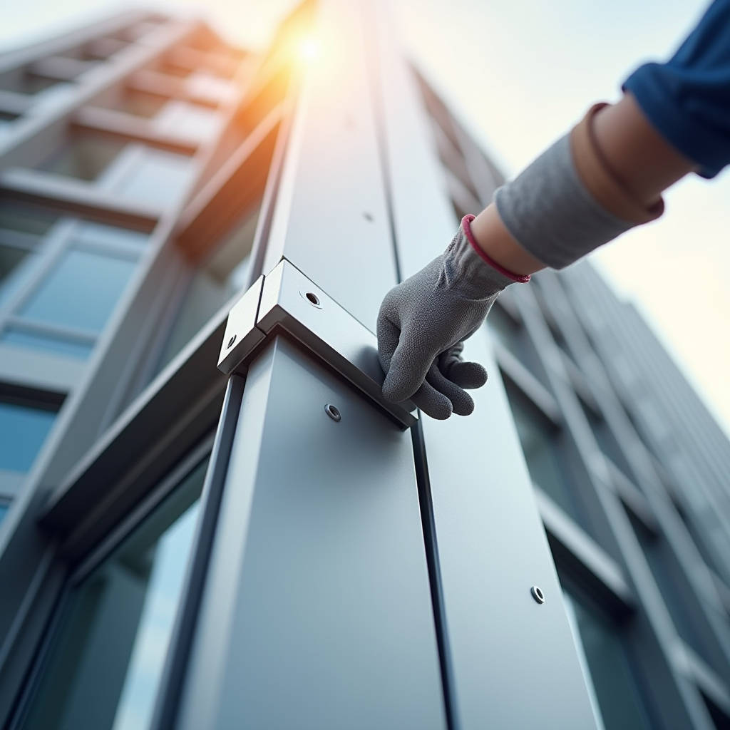
Wind loads don't forgive mistakes. When a solid aluminium panel tears loose from a high-rise at 40 stories, the failure almost never starts in the panel itself. It starts at the connection point. The Aluminum Cladding Anchor is the narrowest bottleneck in the entire façade assembly — a component that might weigh less than 200 grams yet carries responsibility for thousands of kilograms of wind suction, dead load, and thermal movement across decades of service. Engineers who treat anchor selection as an afterthought learn this lesson the hard way, often through water ingress complaints, visible panel warping, or in the worst cases, partial system collapse during a storm. This article examines the structural logic, material compatibility, and installation discipline that separate a durable solid aluminium cladding installation from a latent liability.
Why the Anchor Defines the System
Solid aluminium cladding panels — typically 2.0 mm, 2.5 mm, or 3.0 mm thick sheets with PVDF or FEVE coating — are not self-supporting. They rely entirely on a substructure and an anchoring interface to transfer loads back to the primary building frame. The Aluminum Cladding Anchor sits at the intersection of three distinct engineering domains: structural dynamics, material science, and building physics.
When a gust of wind hits a building face, it doesn't push uniformly. Negative pressure zones form at corners, edges, and parapets, where suction forces can be 2.5 to 3 times higher than the average wind pressure across the elevation. The anchor nearest the building corner might experience 4.2 kN/m² of suction while an anchor 3 meters inward sees only 1.6 kN/m². This differential loading means anchor spacing cannot be uniform across the entire façade — a detail that generic installation guides often miss.
The anchor also manages thermal movement. Aluminium expands at roughly 0.024 mm per meter per degree Celsius. A 4-meter panel subjected to a 60°C temperature swing between summer sun and winter night will move approximately 5.8 mm. If the anchor constrains this movement rigidly, the panel buckles. If it allows too much freedom, the panel rattles. The right Aluminum Cladding Anchor provides controlled restraint: fixed points that handle dead load and lateral forces, sliding points that accommodate thermal expansion without compromising wind resistance.
Anchor Types: A Functional Classification
The market offers dozens of proprietary anchor systems, but they all fall into four functional categories. Understanding which category suits your project is more important than memorizing brand names.
1. Load-Bearing Brackets (Primary Support Anchors)
These carry the dead weight of the panel and transfer it to the vertical substructure or directly to the concrete slab edge. Typically fabricated from 6063-T6 aluminium extrusions or 316 stainless steel, they feature slotted holes for vertical adjustment. A properly designed load-bearing bracket for a 2.5 mm solid aluminium panel weighing approximately 6.8 kg/m² should have a safety factor of at least 3.0 against yield, meaning the bracket must withstand 20.4 kg per square meter of panel it supports without permanent deformation.
In seismic zones, load-bearing anchors require additional capacity. The anchor must resist not only the static dead load but also the inertial forces generated during ground motion. ASCE 7-16 Chapter 13 provides the methodology for calculating these seismic demands on non-structural components. For a building in Seismic Design Category D, the horizontal seismic force on a cladding anchor can exceed 0.4 times the panel weight — a force that acts perpendicular to the anchor's primary load path.
2. Wind Suction Restraints (Secondary Anchors)
Wind suction anchors prevent the panel from being pulled outward. They work in tension rather than shear, and their capacity is governed by the pull-out strength of the fastener into the substructure, the bending strength of the anchor clip, and the bearing strength of the panel edge. A typical wind suction anchor for solid aluminium cladding uses a stainless steel clip that engages a folded or routed edge of the panel, with a minimum engagement depth of 12 mm.
The critical failure mode here is not anchor fracture but pull-out from the aluminium substructure. A self-tapping screw into a 2 mm thick aluminium mullion might achieve only 1.8 kN of pull-out capacity. If the wind suction load on that anchor is 2.5 kN, the math is unforgiving. The solution is either a larger-diameter fastener, a rivet nut that distributes load across a wider area, or a through-bolt with a backing washer — each option carrying different cost and installation time implications.
3. Thermal Expansion Sliding Anchors
These allow in-plane movement along one axis while restraining movement in the perpendicular direction. They typically use a slotted connection with a nylon or PTFE bearing surface to reduce friction. The slot length is calculated based on the expected thermal movement range plus a 3 mm safety margin at each end. For a 3-meter panel in a climate with a 70°C annual temperature swing, the slot needs to accommodate approximately 5.0 mm of movement, meaning a minimum slot length of 11 mm.
Undersized slots are a common defect. The installer tightens the fastener at the midpoint of the slot during installation at 20°C. When the panel reaches 70°C in summer, the edge of the slot contacts the fastener, and further expansion forces the panel to bow outward. This bowing is not a material defect — it's a design error at the anchor level.
4. Combination Fixed-Point Anchors
Every panel needs at least one fixed point that restrains movement in all three axes. This anchor handles dead load, wind load in both directions, and prevents the panel from drifting. All other anchors on the same panel should allow movement in at least one direction. The fixed-point anchor is typically the most heavily loaded and requires the most robust connection to the substrate.
On a 1.5 m × 4 m panel weighing 40.8 kg, the fixed-point anchor at the bottom center might carry 60% of the dead load (24.5 kg) plus the full wind suction load for its tributary area. The anchor design must account for the combined stress from these simultaneous loads, not just each load individually.
Material Compatibility: The Galvanic Corrosion Trap
Solid aluminium panels with PVDF coating are inherently corrosion-resistant — but only if the anchor system doesn't create a galvanic cell. The fundamental rule is straightforward: the anchor material must be either aluminium of a compatible alloy or stainless steel, and a physical barrier must separate dissimilar metals.
The most dangerous combination is a carbon steel anchor clip in direct contact with an aluminium panel in a coastal environment. The steel acts as the cathode, the aluminium as the anode, and salt-laden moisture as the electrolyte. The aluminium corrodes sacrificially, and within 3-5 years, the panel edge around the anchor can thin from 2.5 mm to less than 1.0 mm. The panel hasn't failed — the anchor selection has.
The industry standard solution is 316 stainless steel anchors with a nylon or EPDM isolation pad between the anchor and the panel. 304 stainless steel is acceptable for inland applications but inadequate within 5 km of a coastline, where chloride concentrations demand the molybdenum content of 316. The cost difference between 304 and 316 anchors for a typical mid-rise project might be $2,000-$4,000 — a fraction of the cost of replacing corroded panels after 10 years.
Suppliers like Futeng® have observed that projects specifying 316 stainless steel anchors with PVDF-coated solid aluminium panels in coastal environments report near-zero corrosion-related warranty claims over 15-year periods, compared to significant issues when 304 stainless steel or galvanized steel anchors are substituted.
Anchor Spacing: Engineering Calculations vs. Rules of Thumb
Many installers default to 600 mm spacing for anchors, a rule of thumb inherited from interior panel systems. This is dangerous for exterior cladding. Anchor spacing must be calculated based on three factors: the wind load for the specific building zone, the bending stiffness of the panel, and the capacity of the anchor itself.
Consider a 2.5 mm thick solid aluminium panel (alloy 3003-H14, yield strength 145 MPa) spanning 600 mm between anchors. Under a design wind pressure of 2.0 kPa (typical for a mid-rise building in a moderate wind zone), the bending stress in the panel reaches approximately 52 MPa — well within the yield strength. But if the same panel spans 900 mm, the stress jumps to 117 MPa, approaching the yield point and leaving almost no safety margin.
The calculation changes again at building corners. ASCE 7-16 defines corner zones where wind pressures are amplified by a factor of 1.5 to 2.5 depending on building geometry. If the field-of-wall anchor spacing is 600 mm, the corner zone spacing might need to be 400 mm or even 300 mm. This is not a suggestion — it's a structural requirement that should appear on the engineer's shop drawings.
Below is a practical reference table for anchor spacing based on panel thickness and wind zone:
| Panel Thickness | Wind Zone (kPa) | Max Anchor Spacing (mm) | Anchor Type | Fastener Specification |
|---|---|---|---|---|
| 2.0 mm | ≤ 1.5 (Field) | 500 | Stainless steel clip | M6 SS316, min embed 30 mm |
| 2.0 mm | 2.0-3.0 (Corner) | 350 | Stainless steel clip + backing plate | M8 SS316, min embed 40 mm |
| 2.5 mm | ≤ 1.5 (Field) | 600 | Aluminium bracket 6063-T6 | M6 SS316, min embed 30 mm |
| 2.5 mm | 2.0-3.0 (Corner) | 450 | Aluminium bracket + SS restraint | M8 SS316, min embed 40 mm |
| 3.0 mm | ≤ 1.5 (Field) | 750 | Aluminium bracket 6063-T6 | M6 SS316, min embed 30 mm |
| 3.0 mm | 2.0-3.5 (Corner/High-Rise) | 500 | Aluminium bracket + SS restraint | M8 SS316, min embed 40 mm |
These values assume alloy 3003-H14 or 5052-H32 panels and a substructure capable of transferring loads to the primary structure. For projects using 6061-T6 panels (higher strength but less formable), spacing can be increased by approximately 15% — but only after verification by a licensed structural engineer.
Installation Errors That Compromise Anchor Performance
Even a perfectly specified Aluminum Cladding Anchor fails if installed incorrectly. The most common installation errors are predictable and entirely preventable.
Over-Tightening Fasteners
A stainless steel screw driven too hard into an aluminium substructure strips the threads, reducing pull-out capacity by 40-60%. The installer feels resistance and assumes the connection is solid, but the aluminium has yielded around the threads. The correct approach is torque-controlled driving with a calibrated tool, targeting 70-80% of the proof load for the fastener. For an M6 stainless steel screw into 6063-T6 aluminium, this typically means 8-10 Nm of torque.
Missing Isolation Pads
The nylon or EPDM washer between the anchor clip and the panel is not optional. It prevents galvanic contact, dampens vibration, and allows micro-movement without fretting corrosion. On a 10,000 m² façade, these washers might cost $800 total. Skipping them to save money is a false economy of the highest order.
Incorrect Slot Orientation
Sliding anchors must be oriented so the slot aligns with the direction of expected thermal movement. On a vertical panel, the primary movement is vertical (along the length of the panel). A sliding anchor installed with a horizontal slot provides no relief for vertical expansion. The panel will bow, and the anchor will experience unintended bending moments.
Anchoring Into Inadequate Substrate
The anchor is only as strong as what it's fastened to. A stainless steel bracket rated for 5 kN is useless if it's bolted into a cracked concrete slab edge with only 30 mm of edge distance. The concrete breakout cone governs the failure mode, and in many cases, the anchor capacity is limited not by the anchor itself but by the concrete substrate. Post-installed anchors in concrete must comply with ACI 318 Chapter 17, which requires a minimum edge distance of 1.5 times the embedment depth for anchors loaded in shear toward the edge.
Testing and Verification: Beyond the Specification Sheet
Manufacturer load ratings are a starting point, not a guarantee. Every project should include a testing protocol that verifies anchor performance under conditions specific to the building's substrate and loading.
The minimum testing regime includes pull-out tests on a statistically significant sample of installed anchors — typically 5% of anchors in each wind zone, with a minimum of 10 tests per zone. The test applies a tensile load to 1.5 times the design load and holds for 60 seconds. The anchor must show no displacement greater than 1.0 mm during the hold period.
For high-rise projects or buildings in hurricane-prone regions, dynamic testing is warranted. This involves cyclic loading that simulates wind gust patterns — 500 cycles at 50% of design load, followed by 100 cycles at 100% of design load, followed by a single cycle at 150% of design load. The anchor must survive all cycles without fracture or permanent deformation exceeding 2.0 mm.
Relevant standards include AAMA 501.4 for static load testing of cladding anchors and ASTM E330 for uniform static air pressure difference testing of exterior wall systems. The ISO 16276 series provides guidance on pull-off testing of protective coatings on steel structures, which is relevant when assessing the long-term durability of anchor coatings.
Cost Implications of Anchor Decisions
Anchors represent a small fraction of total façade cost — typically 3-7% of the cladding package — but their influence on long-term performance is disproportionate. Cutting anchor quality to save 2% on the total package is a decision that looks good on the bid spreadsheet and terrible on the 10-year maintenance report.
A real-world comparison: a 5,000 m² solid aluminium cladding project using 2.5 mm PVDF-coated panels. Option A uses 316 stainless steel anchors with EPDM isolation pads, properly spaced per wind zone calculations, with pull-out testing on 5% of anchors. Total anchor-related cost: approximately $42,000. Option B uses 304 stainless steel anchors without isolation pads, at uniform 600 mm spacing, with minimal testing. Total anchor-related cost: approximately $28,000.
The $14,000 saved on Option B translates to roughly $2.80 per square meter. Over a 25-year building lifespan, that's $0.11 per square meter per year. The first time a single panel comes loose in a storm, the emergency repair — including scaffolding, crane mobilization, panel replacement, and engineering investigation — will cost more than the entire anchor budget for the project. And that's before considering the reputational damage to the contractor and the potential liability if the panel injures someone below.
Specifying Anchors for International Projects
For procurement managers sourcing solid aluminium cladding from overseas suppliers, anchor specification requires additional diligence. Different regions have different default practices, and what's standard in one market may be unacceptable in another.
European projects typically reference Eurocode 1 for wind loads and Eurocode 9 for aluminium structures, with anchor testing per ETAG 034 for mechanically fastened cladding systems. North American projects use ASCE 7 for loads, the Aluminum Design Manual for material design, and AAMA testing standards. Middle Eastern projects often reference British Standards (BS 5427 for cladding installation) or a hybrid of Eurocode and ASTM standards.
The anchor system must be specified to match the governing code of the project location, not the supplier's home market. A supplier accustomed to European wind load calculations may underestimate the uplift forces on a building in Miami or Manila. The procurement specification should explicitly state the design wind speed, exposure category, and building risk category per the local code, and require the supplier to demonstrate anchor capacity calculations against these specific values.
The Aluminum Association publishes the Aluminum Design Manual, which provides the material allowables and design methodology for aluminium structural components including anchors. The ASTM B209/B209M standard governs the aluminium sheet and plate used for cladding panels, while AAMA 2605 defines the performance requirements for PVDF coatings on aluminium.
Thermal Performance and the Anchor Connection
Anchor systems create thermal bridges. Every metal connection that penetrates the insulation layer transfers heat between the building interior and exterior. In cold climates, this manifests as cold spots on the interior wall surface and potential condensation. In hot climates, it increases cooling loads.
The thermal impact of an anchor depends on its material, cross-sectional area, and the temperature differential. A stainless steel anchor has roughly one-third the thermal conductivity of an aluminium anchor of the same dimensions. For projects targeting Passive House or similar high-performance standards, stainless steel anchors with thermal break pads are essentially mandatory.
The point thermal transmittance (χ-value) of a typical aluminium cladding anchor without a thermal break is approximately 0.05-0.15 W/K, depending on size. With 100 anchors per floor on a 30-story building, the cumulative thermal bridge effect can add 3-5% to the building's total heating and cooling energy consumption. A thermal break pad made of 10 mm thick rigid PVC or polyamide can reduce the χ-value by 60-80%, paying for itself in energy savings within 3-5 years in most climates.
The anchor's role in the overall building envelope is not just structural. It's also thermal, acoustic, and moisture-related. An anchor that transmits vibration from the panel to the substructure can create audible noise during wind events. An anchor that bridges the drainage cavity can trap water against the panel edge. These secondary functions deserve the same attention as the primary structural role.
Solid aluminium cladding, when anchored correctly, delivers a building envelope that performs reliably for 30-50 years with minimal maintenance. The panels themselves are inert, dimensionally stable, and resistant to UV degradation when properly coated. The anchor is the only component in the system that experiences cyclic stress, environmental exposure, and material interaction simultaneously. Investing engineering attention at the anchor level pays returns across every other aspect of the façade's performance — structural safety, water tightness, thermal efficiency, and long-term durability.