Threaded Welding Stud For Aluminum Cladding Panels Alloy Selection and Weld Process Engineering
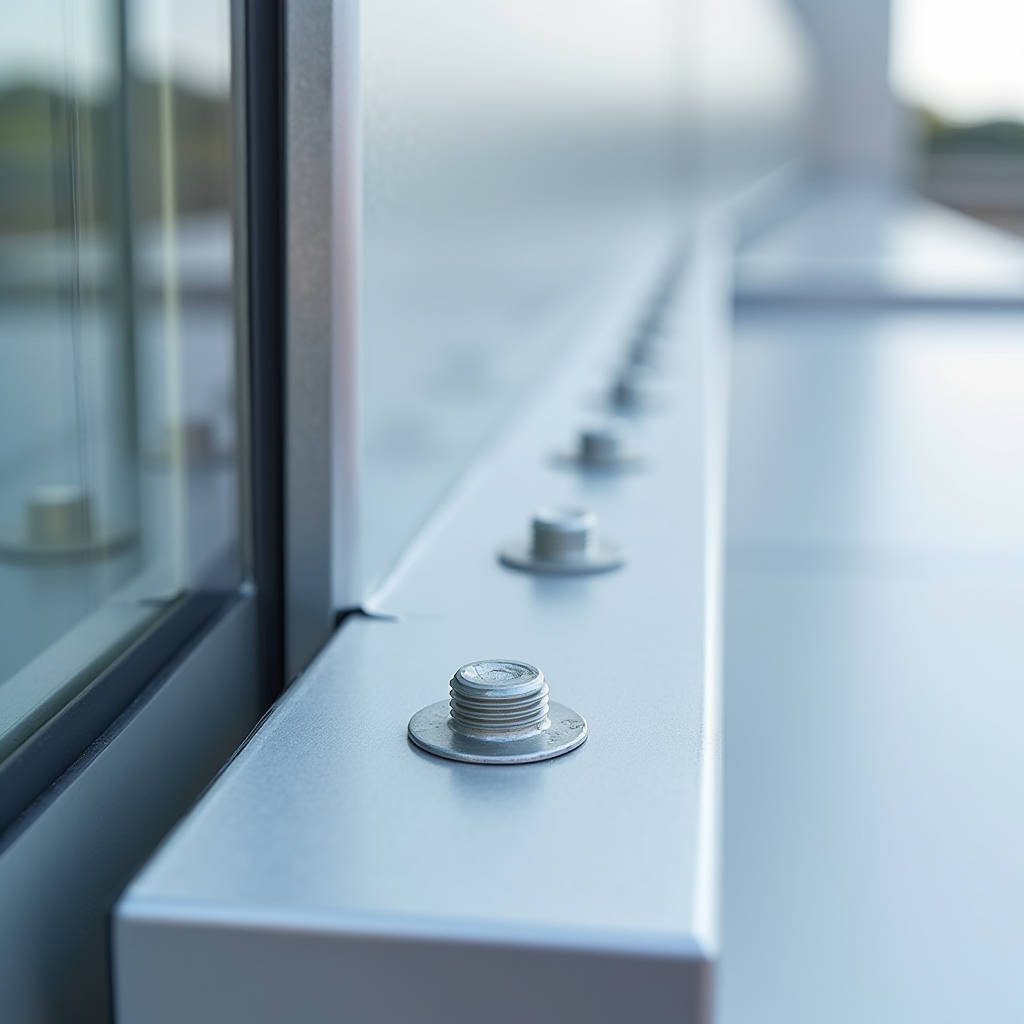
When a façade contractor calls about a failed aluminum panel attachment, the conversation almost always circles back to one overlooked component: the Threaded Welding Stud For Aluminum. These fasteners are the silent workhorses of modern curtain wall systems, transferring wind loads from the cladding face to the substructure without penetrating the visible surface. Unlike bolted connections that require drilling through the panel, a properly specified threaded welding stud preserves the weathertight integrity of solid aluminum sheets while delivering pull-out strengths that can exceed 4,500 N per anchor point. The challenge is that aluminum behaves nothing like steel during the welding cycle — its thermal conductivity is roughly five times higher, its melting point sits around 660°C versus steel's 1,370°C, and the oxide layer that naturally forms on aluminum melts at approximately 2,000°C. This means the stud welding process for aluminum demands a fundamentally different approach to heat input, shielding gas delivery, and surface preparation. Get any of these variables wrong, and the result is a cold joint that looks intact but fails under the first serious wind event.
Why Aluminum Stud Welding Demands a Different Engineering Mindset
Steel stud welding is forgiving. The material's relatively low thermal conductivity allows heat to concentrate at the weld zone, creating a deep, consistent fusion pool. Aluminum flips this equation on its head. The moment an arc strikes an aluminum substrate, heat races away from the weld point at roughly 235 W/m·K — compared to steel's 50 W/m·K. This thermal bleed means the power source must deliver a significantly higher current density in a shorter window to achieve proper fusion before the surrounding metal turns into a heat sink.
The oxide layer complicates matters further. Aluminum oxide (Al₂O₃) forms almost instantly when bare aluminum contacts air, and this ceramic-like skin has a melting point nearly three times that of the base metal. If the oxide isn't removed mechanically or disrupted by the welding arc, it remains as a brittle inclusion at the weld interface. The drawn-arc process with aluminum requires a pilot arc phase specifically designed to scour away this oxide layer before the main welding current flows. This isn't a minor process tweak — it's the difference between a metallurgical bond and a glued joint that will separate under cyclic loading.
For solid aluminum cladding panels in the 2.0mm to 3.0mm thickness range, the Threaded Welding Stud For Aluminum must be specified with a weld base diameter appropriate to the panel gauge. The general rule is that the weld base should not exceed the panel thickness by more than 20% to prevent burn-through while still providing adequate cross-sectional area for load transfer. A 2.5mm panel, for instance, typically pairs with a stud having a weld base diameter between 4.5mm and 5.5mm, depending on the specific alloy and the design wind load for the project location.
Alloy Compatibility: The Metallurgy That Determines Weld Quality
Not all aluminum alloys weld equally well. The 5xxx series (aluminum-magnesium) offers the best stud welding characteristics for architectural applications, which is why 5052, 5754, and 5083 alloys dominate the solid cladding panel market. These alloys provide a favorable balance of formability, corrosion resistance, and weldability. The 3xxx series (aluminum-manganese) such as 3003 and 3004 also welds reliably, though with slightly lower mechanical properties in the heat-affected zone.
The 6xxx series (aluminum-magnesium-silicon) presents a more complex picture. Alloys like 6061 and 6063 are common in extruded substructure components, but when used as cladding sheet, they require careful heat input control. The magnesium-silicon precipitates that give these alloys their strength can dissolve during welding, creating a softened zone adjacent to the weld. Post-weld artificial aging can recover some strength, but this is rarely practical on an installed façade. The Threaded Welding Stud For Aluminum specified for 6xxx series panels should account for the reduced tensile capacity in the heat-affected zone, typically by increasing the number of attachment points or specifying a larger weld base diameter.
One critical specification that often gets overlooked is matching the stud alloy to the panel alloy. Using a 5356 aluminum stud on a 5052 panel creates a compatible metallurgical pair with good corrosion resistance. However, using a 4043 stud (high silicon content) on a 5xxx panel can create a galvanic couple at the weld interface, particularly in marine or industrial environments. The silicon-rich weld metal is cathodic relative to the magnesium-rich base metal, accelerating corrosion at the boundary. This is a failure mode that manifests years after installation, long after the contractor has moved on to other projects.
Drawn-Arc vs. Capacitor Discharge: Selecting the Right Process for Cladding
The two dominant stud welding processes for aluminum cladding are drawn-arc (DA) and capacitor discharge (CD). Each has a specific envelope where it performs best, and selecting the wrong process for the application leads to either inadequate penetration or panel distortion.
Drawn-arc stud welding uses a controlled DC power source, typically in the 400A to 1,500A range for aluminum applications. The process begins with the stud lifted from the workpiece, a pilot arc established to clean the aluminum surface, followed by the main arc that melts both the stud tip and the panel surface. The stud is then plunged into the molten pool under spring or pneumatic pressure. For solid aluminum cladding panels of 2.0mm thickness and above, drawn-arc is generally the preferred method because it provides deeper penetration and a larger weld zone. The weld time for aluminum typically runs between 100ms and 500ms, with the shorter times used for thinner gauges.
Capacitor discharge stud welding stores energy in a capacitor bank and discharges it in a single, extremely brief pulse — typically 1ms to 6ms. This process works well for thin aluminum sheets (0.5mm to 1.5mm) where heat input must be minimized to prevent burn-through. However, for the 2.0mm to 3.0mm solid aluminum panels used in architectural cladding, CD welding often produces insufficient penetration. The weld zone is shallow, and while the stud may hold initially, cyclic wind loading can progressively fracture the limited fusion area. CD welding also struggles with the aluminum oxide problem because the pulse is too brief for effective oxide disruption.
A practical guideline from field experience: if the panel thickness exceeds 1.5mm and the application is structural (supporting wind loads rather than merely locating a component), specify drawn-arc stud welding. The Threaded Welding Stud For Aluminum used in drawn-arc applications will have a slightly different geometry — typically with a small amount of aluminum flux on the tip and a serrated or knurled weld base that helps initiate the arc uniformly.
Surface Preparation Protocols That Prevent Field Failures
The most meticulously specified stud and the most precisely calibrated welding machine cannot compensate for poor surface preparation. Aluminum's oxide layer is the enemy of weld quality, and it must be addressed immediately before welding.
The standard protocol calls for mechanical oxide removal using a clean stainless steel wire brush dedicated exclusively to aluminum work. This brush should never be used on steel or other metals, as cross-contamination embeds iron particles in the aluminum surface that become corrosion initiation sites. The brushing should be performed in one direction (not back-and-forth) and should be done within 30 minutes of welding. Beyond this window, oxide reformation can compromise weld quality.
For PVDF-coated solid aluminum panels, the coating must be completely removed from the weld zone. This is typically done with a rotary tool fitted with a carbide burr or a specialized coating removal bit. The removal area should extend at least 3mm beyond the weld base diameter on all sides. Residual coating in the weld zone vaporizes during arc initiation, creating porosity and gas inclusions that reduce effective weld area. A common field mistake is removing only enough coating to match the stud diameter exactly, leaving a ring of polymer that contaminates the weld pool.
Solvent degreasing follows mechanical preparation. Isopropyl alcohol or acetone applied with a clean, lint-free cloth removes oils, handling residues, and cutting fluids. The solvent must fully evaporate before welding begins. Some contractors skip this step when panels appear clean, but even the oils from handling during installation can create enough contamination to reduce weld strength by 20% to 30%.
Load Capacity Engineering for Wind and Thermal Cycling
The structural performance of a Threaded Welding Stud For Aluminum in a cladding application depends on three failure modes: tensile pull-out of the stud from the panel, shear failure of the stud shank, and panel tearing around the weld zone. Each must be checked against the project's design loads.
Tensile pull-out capacity is primarily a function of the weld zone diameter and the shear strength of the panel material in the heat-affected zone. For a 5052-H32 aluminum panel of 2.5mm thickness with a properly executed drawn-arc weld, the typical tensile capacity ranges from 2,800 N to 4,500 N per stud. This range accounts for variations in weld quality, alloy temper, and the inevitable reduction in strength at the heat-affected zone boundary. The design value should use the lower end of this range unless project-specific testing validates higher numbers.
Shear capacity of the threaded portion depends on the stud's minor diameter and material properties. A standard M8 aluminum stud (5356 alloy) typically provides 3,500 N to 5,000 N in single shear, though the threaded connection to the substructure bracket often governs the assembly's shear capacity rather than the stud itself.
Thermal cycling introduces a loading mechanism that static calculations often miss. Aluminum's coefficient of thermal expansion is approximately 23 × 10⁻⁶ /°C — roughly twice that of steel. A 3-meter aluminum panel subjected to a 60°C temperature swing (from -10°C on a winter night to 50°C under summer sun) expands by approximately 4.1mm. If the stud connections constrain this movement completely, thermal stresses can reach 50 MPa or more, which approaches the fatigue limit for many aluminum alloys. The solution is to design the attachment system with controlled flexibility — typically through slotted connections at the bracket level — so that the Threaded Welding Stud For Aluminum itself is not required to accommodate panel expansion through bending.
Corrosion Considerations Across Climate Zones
Aluminum's natural corrosion resistance comes from its oxide layer, but the weld zone represents a discontinuity in this protective film. The fusion zone has a cast microstructure different from the wrought panel, and the heat-affected zone may have altered precipitation states that affect local corrosion potential.
In coastal and marine environments, chloride exposure accelerates pitting corrosion at microstructural discontinuities. The weld zone, with its heterogeneous composition, can become anodic relative to the surrounding panel material. This is particularly problematic when the stud alloy differs significantly from the panel alloy. The best practice for marine environments is to match the stud alloy as closely as possible to the panel alloy — 5356 studs on 5xxx panels, for instance — and to apply a protective coating over the completed weld.
For industrial environments with sulfur dioxide or nitrogen oxide exposure, the weld zone's corrosion resistance depends more on the overall alloy composition than on microstructural effects. The 5xxx series alloys with magnesium content below 3.5% (such as 5052 and 5754) generally perform well. Alloys with higher magnesium content (5083, 5086) can become sensitized if the welding heat input is excessive, leading to intergranular corrosion at grain boundaries. The solution is strict heat input control and, for critical applications, specifying alloys with controlled sensitization resistance.
Futeng® has documented corrosion performance data for welded stud connections on solid aluminum panels across projects in Southeast Asia, the Middle East, and Northern Europe, providing empirical validation that properly specified and executed stud welds maintain their integrity through decades of environmental exposure without requiring supplementary protection beyond the standard PVDF or powder coating system.
Quality Verification Methods That Catch Problems Before Installation
Visual inspection alone cannot determine whether a Threaded Welding Stud For Aluminum has achieved full fusion. The weld fillet may look uniform and complete while hiding a cold joint underneath. Several verification methods are available, ranging from simple field tests to laboratory-grade analysis.
The bend test is the most practical field verification method. A section of threaded rod or a nut is attached to the welded stud, and the stud is bent through a specified angle — typically 15° to 30° for aluminum studs — using a hollow tube or purpose-built bending tool. A properly fused stud will bend without cracking at the weld interface. If the stud breaks cleanly at the weld line with minimal deformation, the joint was cold and lacked proper fusion. This test is destructive, so it's performed on sample panels or on a statistical sampling basis during production.
Torque testing provides a non-destructive alternative for threaded studs. A calibrated torque wrench applies a specified torque (typically 50% to 70% of the stud's rated torque capacity) to verify that the weld can sustain the required clamping force for bracket attachment. The test torque should be specified in the project's quality control documentation and should account for the stud material, thread size, and the lubrication condition of the threads.
For critical applications or when establishing welding parameters for a new panel/stud combination, macro-etch testing provides definitive weld quality data. A cross-section of the welded stud is cut, polished, and etched with a suitable reagent (typically Keller's reagent for aluminum) to reveal the fusion zone microstructure. The etch will show the depth of penetration, the extent of the heat-affected zone, and any defects such as porosity, lack of fusion, or oxide inclusions. While this is a laboratory test rather than a field procedure, it should be part of the pre-production qualification process for any significant cladding project.
Specification Parameters for Procurement Documents
When writing a procurement specification for threaded welding studs, the level of detail directly correlates with the quality of the product delivered. A vague specification that reads "aluminum weld studs, M8" will result in the cheapest commodity product that meets the literal words but may fail in service. A proper specification addresses the following parameters:
- Stud alloy and temper: Specify the aluminum alloy (e.g., 5356, 5052, 4043) and temper condition. For structural cladding applications, 5356-H32 or 5052-H32 are common choices.
- Thread specification: Define the thread standard (ISO metric, UNC, UNF), thread class (typically 6g for external threads), and thread length. The thread length must accommodate the bracket thickness plus the nut height plus at least two thread pitches of protrusion.
- Weld base geometry: Specify the weld base diameter, the flange thickness if applicable, and any special features such as flux loading or ignition tip geometry.
- Mechanical properties: Reference the minimum tensile strength, yield strength, and elongation for the stud material. For 5356 aluminum, typical minimum values are 240 MPa tensile and 110 MPa yield.
- Surface condition: Specify whether the studs are supplied as-formed, cleaned, or with a protective coating. Aluminum studs should be free from heavy oxide, oil, and other contaminants.
- Applicable standards: Reference relevant standards such as ISO 13918 for stud welding, ASTM B211 for aluminum bar and rod, and AAMA guidelines for aluminum curtain wall attachment.
The procurement specification should also address packaging and handling requirements. Aluminum studs are softer than steel and more susceptible to thread damage during shipping. Bulk packaging in plastic bags within rigid containers is preferable to loose bulk shipment. The specification should also require lot traceability — each container marked with the heat number, production date, and alloy designation — to support quality investigations if field problems arise.
Comparative Analysis of Stud Welding Parameters by Panel Thickness
The table below consolidates practical welding parameters for drawn-arc stud welding on solid aluminum cladding panels. These values are based on 5356 alloy studs on 5052-H32 panel material and should be verified through pre-production testing for each specific project combination.
| Panel Thickness | Stud Weld Base Diameter | Welding Current (A) | Weld Time (ms) | Lift Height (mm) | Typical Tensile Capacity (N) | Recommended Thread Size |
|---|---|---|---|---|---|---|
| 2.0 mm | 4.5 mm | 450 - 550 | 100 - 150 | 1.5 - 2.0 | 2,200 - 3,200 | M6 |
| 2.5 mm | 5.0 - 5.5 mm | 550 - 700 | 120 - 200 | 1.8 - 2.5 | 2,800 - 4,500 | M8 |
| 3.0 mm | 6.0 - 7.0 mm | 700 - 900 | 180 - 300 | 2.0 - 3.0 | 4,000 - 6,500 | M8 / M10 |
| 4.0 mm | 7.5 - 8.5 mm | 850 - 1,100 | 250 - 400 | 2.5 - 3.5 | 5,500 - 8,500 | M10 / M12 |
These parameters assume proper surface preparation, argon shielding gas at 8-12 L/min flow rate, and ambient temperature between 5°C and 35°C. Welding outside these temperature ranges requires parameter adjustment — colder conditions demand higher current or longer weld time to compensate for increased heat loss to the surrounding material. The tensile capacity values represent the range observed in production-quality welds; design values should incorporate a safety factor of at least 3.0 for static loads and higher for fatigue-critical applications.
Common Installation Errors and Their Root Causes
Field experience reveals a consistent pattern of installation errors that compromise the performance of welded stud connections on aluminum cladding. Understanding these failure modes helps specifiers write better quality control procedures and helps contractors train their installation teams.
Insufficient grounding is the most frequent cause of inconsistent weld quality. The welding current must flow from the stud welding gun through the panel and back to the power source through a ground clamp. If the ground connection is loose, corroded, or placed too far from the weld point, the current path includes unintended resistance that reduces the effective welding current. On aluminum panels, the ground clamp should be placed within 300mm of the weld location and should make contact with clean, bare metal — not on a coated or anodized surface. Some contractors use a dedicated ground plate clamped to the panel edge, but this arrangement can still introduce resistance if the panel-to-plate contact is compromised by coating or oxide.
Arc blow — the deflection of the welding arc by magnetic fields — is a less common but more insidious problem with aluminum stud welding. The higher currents used for aluminum (compared to steel) create stronger magnetic fields around the workpiece and cables. If the ground cable is routed in a way that creates an asymmetric magnetic field at the weld point, the arc can be deflected, producing an uneven weld fillet and incomplete fusion on one side. The solution is to route the ground cable symmetrically relative to the weld location or to use a split ground connection with two cables on opposite sides of the weld point.
Moisture on the panel surface is a problem that appears trivial but has serious consequences. Aluminum panels stored outdoors or in unconditioned spaces can accumulate condensation, particularly when moved from a cold storage area to a warm fabrication shop. Water at the weld interface flashes to steam during arc initiation, creating porosity in the weld and potentially ejecting molten metal from the joint. Panels should be stored in dry conditions for at least 24 hours before welding, and any visible moisture should be removed with compressed air and allowed to evaporate completely before the welding gun is positioned.
Integrating Stud-Welded Connections into the Broader Cladding System
A Threaded Welding Stud For Aluminum does not function in isolation. It is one component in a load path that extends from the panel face through the stud, the bracket, the adjustable connection, and into the building's structural frame. Each interface in this chain must be designed with compatible materials, appropriate tolerances, and a clear understanding of how the assembly will behave under thermal movement, wind loading, and seismic displacement.
The bracket that attaches to the welded stud is typically aluminum or stainless steel. Aluminum brackets eliminate galvanic corrosion concerns and provide consistent thermal expansion behavior, but they require greater section thickness to achieve the same strength as steel. Stainless steel brackets (typically 304 or 316 grade) offer higher strength in a smaller profile but introduce a galvanic couple with the aluminum stud. The standard mitigation is a non-conductive isolation washer or bushing at the stud-to-bracket interface, combined with a stainless steel fastener that is similarly isolated from the aluminum bracket if one is used.
The adjustable connection between the bracket and the building structure — typically a slotted hole with a bolted connection — must accommodate the differential movement between the cladding and the structure. The slot length should be calculated based on the expected thermal expansion range, the panel dimensions, and the distance between fixed and sliding attachment points. A common specification error is to make all connections sliding, which leaves the panel without a defined fixed point. The result is that the panel can drift over time, accumulating displacement in one direction until it binds against adjacent panels or building elements. The correct approach is to designate one stud connection as the fixed point (with a round hole rather than a slot) and allow the remaining connections to slide.
For projects specifying solid aluminum panels in the 2.5mm to 3.0mm range with PVDF coating systems, the stud welding process must be completed before the panels receive their final coating. Welding through a cured PVDF coating is not feasible — the coating burns, contaminates the weld, and creates a corrosion-prone zone around the stud. The standard fabrication sequence is: cut and form the panel, weld the studs, clean and prepare the entire panel surface, apply the pretreatment and primer, and then apply the PVDF topcoat. The coating masks the weld zone, so the stud locations must be clearly documented for the installation team. Some fabricators apply a small contrasting mark on the coated surface to indicate stud positions, which helps the installation crew locate the attachment points without damaging the coating.
Documentation from the American Architectural Manufacturers Association provides additional guidance on attachment design for aluminum curtain wall components, including recommended safety factors and testing protocols. The ISO 13918 standard covers the dimensional and mechanical requirements for weld studs, while ASTM B209 governs the aluminum sheet material itself. These references, combined with project-specific testing and the fabricator's documented quality control procedures, form the technical basis for a reliable stud-welded cladding attachment system.
The decision to use welded studs rather than alternative attachment methods — adhesive bonding, mechanical fasteners through the panel face, or perimeter clamping systems — should be based on a clear-eyed assessment of the project's requirements. Welded studs offer the advantage of a concealed connection that preserves the panel's visual integrity and weathertightness. The trade-off is that the welding process requires skilled operators, rigorous quality control, and a fabrication sequence that accommodates pre-coating welding. For high-end architectural projects where the panel surface must remain uninterrupted and the structural demands are significant, the Threaded Welding Stud For Aluminum remains the attachment method that delivers the most reliable long-term performance. The key is not just specifying the right stud, but building the entire system — from alloy selection through surface preparation, welding parameters, quality verification, and installation detailing — around the specific demands of aluminum as a substrate.