Pop Rivet For Aluminum Panel Engineering Guide for Solid Cladding Facade Systems
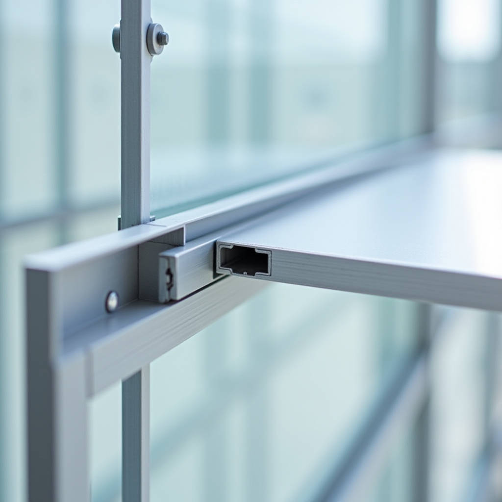
When fastening solid aluminum cladding panels to a curtain wall substructure, the Pop Rivet For Aluminum Panel decision carries more weight than most project engineers initially assume. A blind rivet that works perfectly on a 0.063-inch aluminum sheet metal flashing will fail catastrophically when asked to secure a 3.0mm PVDF-coated solid aluminum panel spanning 1,200mm between mullions. The failure mode is rarely the rivet body itself. More often, the problem traces back to galvanic corrosion between the steel mandrel and the aluminum substrate, or to thermal expansion stresses that the rivet's grip range was never designed to accommodate. This article addresses the specific engineering considerations that matter when selecting pop rivets for solid aluminum cladding — not for thin-gauge trim, not for composite panels, and not for interior applications. We are looking at exterior-grade, structural and semi-structural fastening of solid 2.0mm to 3.0mm aluminum sheets in high-rise and commercial facade systems.
Why Solid Aluminum Panels Demand a Different Fastener Conversation
Solid aluminum cladding panels — typically 2.0mm, 2.5mm, or 3.0mm thick, finished with PVDF (polyvinylidene fluoride) coatings meeting AAMA 2605 specifications — operate in a fundamentally different mechanical environment than the aluminum trim coil and gutter materials that dominate general pop rivet marketing. A 3.0mm solid aluminum panel measuring 1,500mm × 3,000mm weighs approximately 36.5 kg. When wind loads hit 2.5 kPa (a typical design pressure for mid-rise buildings in many regions), the tension and shear forces transferred to each fastener point are not trivial.
Most off-the-shelf aluminum pop rivets sold through industrial supply catalogs are designed with grip ranges optimized for joining two thin sheets — think 0.5mm to 1.5mm combined thickness. The mandrel break load, the shear strength rating, and the body material are all calibrated for that range. When you introduce a 2.5mm solid aluminum panel being fastened to a 3mm or 4mm aluminum extrusion subframe, the total grip thickness jumps to 5.5mm or more. This immediately eliminates a large portion of standard blind rivets from consideration.
The second issue is less obvious: thermal cycling. Solid aluminum panels expand and contract at roughly 23.6 × 10⁻⁶ per °C. On a 3-meter panel subjected to a 60°C temperature swing between summer sun and winter night, the linear expansion is approximately 4.25mm. A rivet that clamps too rigidly without allowing for micro-movement will eventually work-harden the surrounding aluminum, leading to fatigue cracks radiating from the fastener hole. This is not a theoretical concern — it is a documented failure mode in facade engineering.
Material Compatibility: The Galvanic Corrosion Problem Nobody Discusses
Walk through any industrial fastener catalog and you will find aluminum pop rivets with steel mandrels. These are the industry standard because steel mandrels provide higher tensile strength during setting and a more predictable break load. But in exterior aluminum cladding applications, that steel mandrel remnant — the small portion that remains locked inside the set rivet body — becomes a corrosion initiation point.
The mechanism is straightforward: when moisture penetrates the joint (and it will, over decades of rain and condensation cycles), the steel mandrel and the aluminum rivet body form a galvanic couple. The aluminum, being more anodic, sacrifices itself. The result is pitting corrosion that starts inside the rivet body and propagates outward, eventually compromising the fastener's shear capacity. This is particularly aggressive in coastal environments where chloride ions accelerate the electrochemical reaction.
The engineering solution is to specify all-aluminum blind rivets — where both the body and the mandrel are aluminum alloy. The trade-off is a lower mandrel break load, which means slightly lower clamping force. But for solid aluminum cladding panels, where the substrate is not compressible like a composite core, the clamping force requirement is different. What matters more is maintaining consistent contact pressure across decades of thermal cycles without introducing a dissimilar metal corrosion cell.
For projects within 5 kilometers of a coastline, this specification becomes non-negotiable. The ASTM B117 salt spray test results for aluminum-steel rivet combinations show visible corrosion at the mandrel-body interface within 500 hours. All-aluminum rivets under the same conditions typically exceed 1,000 hours before showing significant degradation. Some manufacturers, including Futeng®, have moved toward specifying all-aluminum fasteners as standard for their solid aluminum panel systems in marine environments.
Grip Range and Hole Size: The Numbers That Determine Field Success
Grip range is the single most misunderstood parameter in blind rivet selection. The grip range is the total thickness of materials the rivet can effectively join. If the actual grip falls below the minimum grip range, the rivet will not set properly — the mandrel head will not draw the rivet body tight against the blind side. If the actual grip exceeds the maximum grip range, the rivet body may not have enough length to form a proper blind-side bulb, resulting in a weak joint that can pull through under load.
For a typical solid aluminum cladding installation — say, a 2.5mm panel fastened to a 4mm aluminum extrusion subframe — the total grip is 6.5mm. The rivet specification must list a grip range that comfortably brackets this value, ideally with the actual grip falling in the middle third of the range. A rivet rated for 4.8mm to 7.9mm grip would be appropriate here. One rated for 1.6mm to 4.8mm would not.
Hole diameter is equally critical and equally prone to field errors. The standard hole size for a 4.8mm (3/16-inch) diameter blind rivet is 4.9mm to 5.1mm. Drill the hole oversize — a common result when installers use worn drill bits or rush the process — and the rivet body will not expand sufficiently to fill the hole, reducing shear strength by 20% to 40%. Drill it undersize and the rivet will be difficult to insert, leading to installation delays and the temptation to hammer the rivet into place, which damages the mandrel and compromises the setting process.
On large-scale projects, we recommend that the construction team maintain a drill bit replacement schedule and verify hole diameters with a go/no-go gauge at the start of each shift. This adds perhaps 15 minutes to the morning routine and prevents fastener failures that could require panel removal and replacement — a cost that dwarfs any savings from stretching drill bit life.
Shear and Tensile Strength: What the Catalog Numbers Actually Mean
Manufacturers publish shear strength and tensile strength values for their blind rivets, but these numbers require context. The published shear strength is typically the ultimate shear strength — the force at which the rivet body fails in single shear. The published tensile strength is the force required to pull the mandrel head through the rivet body or to fracture the rivet body in tension.
Neither number accounts for the behavior of the joined materials. In solid aluminum cladding, the limiting factor is often not the rivet itself but the bearing strength of the aluminum panel around the fastener hole. For a 2.5mm-thick 3003-H14 aluminum panel, the bearing capacity around a 5mm hole is approximately 2.1 kN based on a bearing stress limit of 170 MPa. If the rivet's published shear strength is 2.5 kN, the joint design is bearing-limited — the panel material will deform before the rivet shears.
This has practical implications for fastener spacing. The common rule of thumb — one fastener every 300mm to 400mm along panel edges — assumes a certain wind load and panel thickness. For high-wind regions or taller buildings where wind pressures increase with height, the spacing should be calculated rather than assumed. The calculation is straightforward:
Fastener spacing (mm) = (Fastener allowable load in kN × 1000) / (Design wind pressure in kPa × panel width in meters)
For a 2.5 kPa design pressure, a 1.2-meter panel width, and a fastener with an allowable load of 1.0 kN (applying a safety factor of 2.5 to the ultimate strength), the maximum spacing works out to 333mm. This aligns with the common rule of thumb, but the calculation confirms it rather than relying on tradition.
Thermal Expansion: Designing Joints That Breathe
Solid aluminum panels move. This is not a defect — it is a physical property of the material. The challenge for the fastener specification is to accommodate this movement without compromising the weather seal or the structural integrity of the connection.
There are two approaches used in practice. The first is to use a rivet with a slightly oversized hole on the panel side, combined with a nylon or EPDM washer that allows the panel to slide relative to the substructure. This approach works well for panels up to about 2 meters in length. The washer absorbs the differential movement while the rivet maintains clamping force.
The second approach, more common for larger panels, is to use a combination of fixed points and sliding points. Fixed points use standard rivets in standard holes. Sliding points use rivets installed through slotted holes in the panel, oriented parallel to the direction of expected expansion. The slot length is calculated based on the expected thermal movement, typically 1.5 to 2 times the calculated expansion to provide a safety margin.
The following table summarizes the thermal expansion considerations for different panel dimensions:
| Panel Length (mm) | Temp Range (°C) | Linear Expansion (mm) | Recommended Slot Length (mm) | Fastener Strategy |
|---|---|---|---|---|
| 1,000 | -20 to +60 | 1.89 | 3.5 | Standard rivets with EPDM washers |
| 2,000 | -20 to +60 | 3.78 | 7.0 | Fixed + sliding point combination |
| 3,000 | -20 to +60 | 5.66 | 10.0 | Fixed + sliding point combination |
| 3,000 | -10 to +80 | 6.37 | 12.0 | Fixed + sliding point, all-aluminum rivets |
Note that the temperature range accounts for both ambient air temperature and solar radiation heating. A dark-colored PVDF coating can reach surface temperatures 30°C to 40°C above ambient air temperature in direct sunlight, a factor that is sometimes overlooked in expansion calculations.
Installation Quality: The Variable That Overrides Every Specification
You can specify the perfect rivet — correct material, correct grip range, correct diameter — and still end up with joint failures if the installation is done poorly. The most common installation errors on solid aluminum cladding projects include:
- Over-setting: Applying too much pressure with the rivet tool, which can deform the panel surface around the fastener head. On PVDF-coated panels, this creates a visible depression that catches light differently and becomes an aesthetic defect.
- Under-setting: Not pulling the mandrel completely, leaving the rivet body partially expanded and the joint loose. This is often caused by using a manual rivet tool on a large number of fasteners — installer fatigue leads to incomplete setting.
- Angle deviation: Installing the rivet at an angle to the panel surface rather than perpendicular. This creates uneven clamping pressure and can cause the rivet head to sit proud on one side.
- Contamination: Installing rivets through wet sealant or with debris in the hole. The sealant can lubricate the rivet body during setting, reducing the mechanical interlock, or it can cure around the mandrel and prevent proper break-off.
For projects exceeding 5,000 square meters of cladding area, the economics strongly favor pneumatic or cordless electric rivet tools over manual tools. A quality cordless rivet tool — such as those from established manufacturers serving the professional market — costs between $800 and $2,500 but delivers consistent setting force across thousands of installations. The reduction in rework alone typically justifies the investment within the first week of installation.
Pull-out testing should be conducted on-site at the start of installation and at regular intervals thereafter. A minimum of five test rivets per 1,000 installed is a reasonable benchmark. The test involves installing rivets in the actual panel and subframe materials, then measuring the force required to fail the joint. If the failure mode changes — for example, from rivet shear to panel tear-out — the installation parameters should be reviewed before proceeding.
Coating Integrity: Protecting the PVDF Finish Around Fastener Holes
When you drill a hole through a PVDF-coated solid aluminum panel, you create a raw aluminum edge that is exposed to the elements. This edge has no coating protection and becomes a potential corrosion initiation site. The fastener itself — whether a rivet head or a screw head — provides some protection, but the area immediately around the fastener head is vulnerable.
The industry standard approach is to apply a small amount of neutral-cure silicone sealant to the rivet body before installation, or to inject sealant into the drilled hole. As the rivet is set, the sealant fills the annular space between the rivet body and the hole wall, sealing the raw edge from moisture. The sealant must be neutral-cure (not acetoxy-cure) because acetic acid released during curing of acetoxy silicones can attack the PVDF coating and the aluminum substrate.
For projects specifying AAMA 2605-compliant PVDF coatings — which carry a 20-year performance warranty from reputable coating suppliers — the fastener installation method must be documented and approved as part of the overall coating warranty. Some coating manufacturers require specific sealant types and application methods. Overlooking this detail can void the coating warranty, leaving the building owner with no recourse if the coating fails prematurely.
Specifying Pop Rivets For Aluminum Panel Projects: A Practical Checklist
Based on the technical considerations discussed above, the following checklist can be used when preparing fastener specifications for solid aluminum cladding projects:
- Confirm panel thickness and alloy: Document whether panels are 2.0mm, 2.5mm, or 3.0mm, and the specific alloy (commonly 3003, 3004, or 5052 for architectural applications).
- Calculate total grip thickness: Panel thickness plus subframe thickness plus any shim or thermal break material.
- Select rivet material: All-aluminum for coastal or high-corrosion environments; aluminum body with aluminum mandrel as minimum; avoid steel mandrels within 5km of coastline.
- Verify grip range: Ensure the actual grip falls within the middle third of the rivet's specified grip range.
- Check shear and tensile ratings: Compare against calculated loads with appropriate safety factors (typically 2.5 to 3.0 for facade applications).
- Address thermal movement: Determine whether fixed-only or fixed-plus-sliding fastener strategy is required based on panel dimensions and expected temperature range.
- Specify installation tools: Pneumatic or cordless electric for projects over 5,000 m²; manual tools acceptable for smaller areas with quality control checks.
- Document sealant requirements: Neutral-cure silicone for hole sealing; verify compatibility with coating warranty.
- Plan for testing: On-site pull-out testing at start of installation and at regular intervals.
- Include drill bit specifications: Hole diameter tolerance and replacement schedule.
For projects where the engineering team wants a single-source supplier that can provide both the solid aluminum panels and the compatible fastening system, manufacturers like Futeng® offer pre-engineered fastener packages matched to their panel specifications. This approach reduces the risk of field mismatches between panels and fasteners and simplifies the procurement process for the general contractor.
When Standard Solutions Fall Short: Custom Rivet Specifications
There are situations where catalog rivets do not meet the project requirements. Large-format panels with unusual thicknesses, projects in extreme climate zones, or facade designs with complex geometry may require custom rivet specifications.
Custom specifications typically involve adjusting the rivet body length to achieve a specific grip range, selecting a non-standard mandrel material, or specifying a particular head style (large flange heads are sometimes used to distribute clamping pressure over a wider area on thinner panels). The minimum order quantities for custom blind rivets are generally in the range of 50,000 to 100,000 pieces, which makes this option viable for large commercial projects but impractical for small installations.
Lead times for custom rivets range from 6 to 12 weeks depending on the manufacturer and the complexity of the specification. This needs to be factored into the project schedule early — discovering during installation that standard rivets are unsuitable leads to delays that can cost far more than the rivets themselves.
For reference, the relevant standards governing blind rivet performance include ISO 14589 (Blind rivets — Mechanical testing) and the IFI (Industrial Fasteners Institute) standards for inch-series fasteners. Project specifications should reference these standards to ensure that all parties are working to the same performance criteria.
Cost Considerations That Go Beyond the Rivet Price
The purchase price of pop rivets is a tiny fraction of the total installed cost of a solid aluminum cladding system. A 3/16-inch all-aluminum blind rivet might cost $0.08 to $0.25 per piece depending on quantity and specification. On a 10,000 m² facade with fasteners at 350mm spacing, the total rivet count might be 80,000 to 100,000 pieces, representing a material cost of $8,000 to $25,000. On a cladding package worth $1.5 million to $3 million, the fastener cost is less than 2% of the total.
The real cost driver is not the rivet price but the consequences of fastener failure. Replacing a single damaged solid aluminum panel on a completed building typically costs between $500 and $2,500 depending on access requirements (scaffolding, boom lifts, or rope access), the panel size, and whether the replacement panel needs to be custom-fabricated to match the existing finish. If a systemic fastener problem requires replacing 50 panels across a facade, the cost can easily exceed $100,000.
This math makes a compelling case for investing in higher-quality fasteners and more rigorous installation quality control. Saving $2,000 on rivet costs by choosing a marginally cheaper specification is a false economy when the downside risk is measured in six figures.
The same logic applies to the choice between manual and powered installation tools. A $1,500 cordless rivet tool that prevents over-setting and under-setting across 80,000 installations pays for itself if it prevents even two panel replacements.
Engineering Judgment Over Catalog Selection
The selection of a Pop Rivet For Aluminum Panel on a commercial facade project should never be reduced to picking a part number from a catalog. The decision sits at the intersection of structural engineering, materials science, corrosion chemistry, and construction quality management. The rivet that works on a small residential gutter installation has almost nothing in common with the rivet that will secure a 3-meter solid aluminum panel to a high-rise curtain wall for 30 years of service life.
The core engineering priorities are clear: match the grip range to the actual material stack-up, eliminate galvanic couples by specifying all-aluminum construction, account for thermal movement through joint design rather than hoping the fastener will accommodate it, and enforce installation quality through tooling specifications and on-site testing. Each of these priorities is individually manageable. Together, they form a reliable basis for fastener specification that protects both the facade's structural integrity and the project's commercial outcome.
For engineers and procurement managers navigating these decisions, the most valuable resource is often the technical documentation provided by the panel manufacturer. When the panel supplier and the fastener specification are developed together — rather than independently — the result is a system where the components are verified to work as an assembly, not just as individual parts that happen to share a bill of materials.