Blind Rivet For Aluminum Panel Engineering Loads Corrosion and Installation Standards
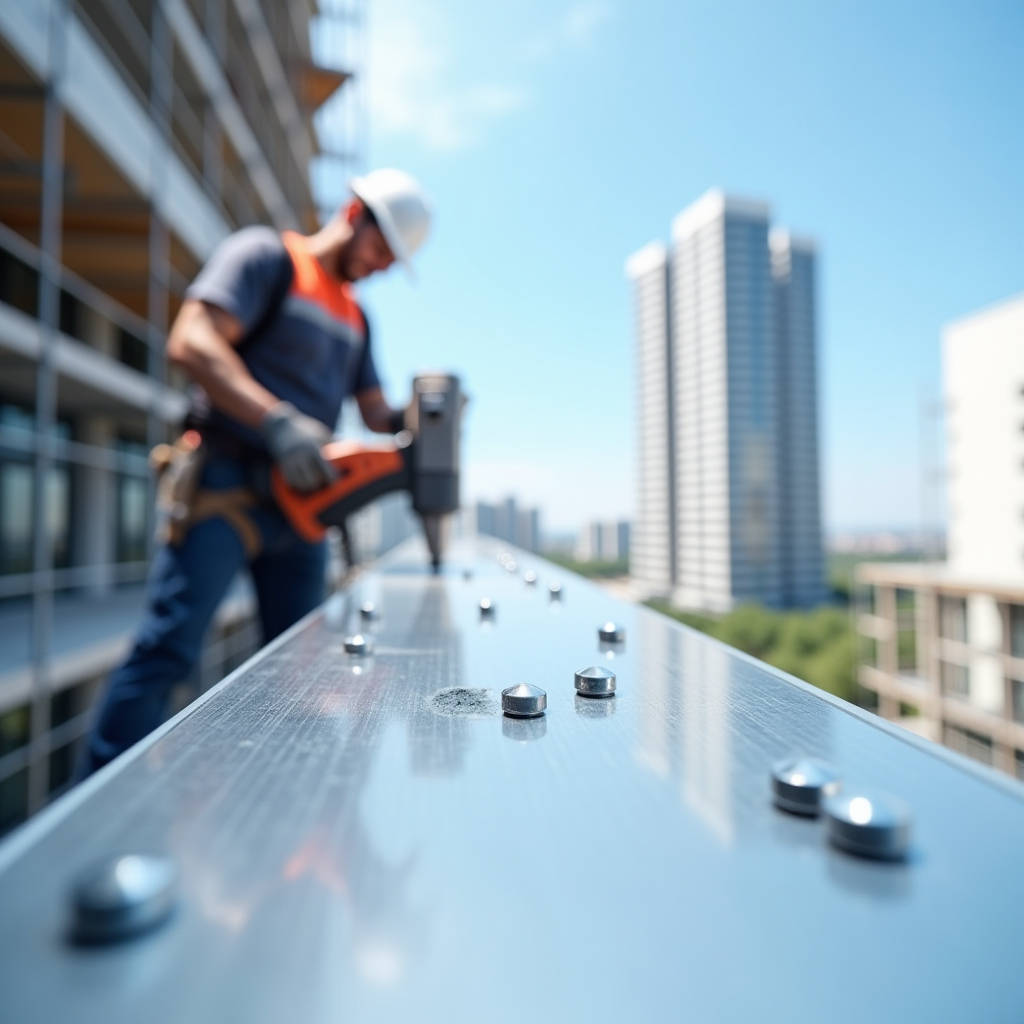
When securing solid aluminium cladding panels to a curtain wall substructure, the blind rivet for aluminum panel applications often becomes the default choice—and for good reason. A properly specified blind rivet eliminates the need for two-sided access, speeds up installation on high-rise facades, and when matched correctly to the panel alloy, delivers a joint that resists galvanic corrosion for decades. But the decision tree runs deeper than picking a 5052 aluminium rivet off a shelf. Panel thickness, wind load, thermal movement, and the substrate material behind the panel all dictate whether the fastener holds or fails. This article unpacks the engineering logic behind blind rivet selection for solid aluminium cladding—specifically 2.0mm to 3.0mm thick PVDF-coated panels—and walks through the failure modes, installation standards, and procurement strategies that separate a 30-year facade from one that needs rework in five.
Why Blind Rivets Dominate Aluminium Cladding Fastening
Solid aluminium cladding panels—typically 2.0mm, 2.5mm, or 3.0mm thick sheets of alloy 1100, 3003, or 5052—arrive on site pre-cut and pre-coated. The installer fixes them to a steel or aluminium subframe using mechanical fasteners. Blind rivets dominate this space because they solve a fundamental access problem: once the panel is positioned against the substructure, the back side is unreachable. A blind rivet sets from the front face only, expanding behind the workpiece to form a secure clinch. No welding, no bolting with a nut on the blind side, and no adhesive curing time.
The Chobert-style blind rivet, referenced in structural aluminium guides, uses a tapered mandrel drawn through a hollow shank to flare the tail. For cladding, the more common variant is the open-end blind rivet with a domed head, set using a pneumatic or battery-powered rivet tool. The cycle time per rivet runs under three seconds, making it practical for facades requiring thousands of fasteners.
But speed is not the only factor. In rainscreen and pressure-equalized wall systems, the fastener must accommodate differential thermal movement between the aluminium panel and the steel subframe. Aluminium expands at roughly 23 × 10⁻⁶ /°C versus 12 × 10⁻⁶ /°C for carbon steel. A 3-meter panel subjected to a 50°C temperature swing will move approximately 3.5mm relative to the steel behind it. Rigid fastening cracks panels or shears rivets. This is where blind rivet selection intersects with slot geometry and gasket design.
Material Compatibility: The Galvanic Corrosion Trap
Every blind rivet for aluminum panel installations sits at the intersection of three materials: the rivet body, the rivet mandrel, and the substrate. The aluminium cladding panel itself is usually alloy 1100 or 3003 with a PVDF (polyvinylidene fluoride) coating at 25–35 microns dry film thickness over a chromate conversion coating. The substructure varies—galvanized steel, extruded aluminium, or stainless steel. The rivet introduces its own alloy into this electrochemical stack.
The most common mistake in cladding fastener specification is pairing an aluminium rivet body with a carbon steel mandrel in an outdoor application. The steel mandrel stem, exposed after setting, sits proud of the rivet head. In the presence of moisture, the steel becomes cathodic relative to the aluminium panel, and the panel corrodes sacrificially around the fastener hole. Within three to five years, white corrosion product appears around rivet heads. Within ten years, the panel loses structural integrity at the fastening point.
The correct specification for solid aluminium cladding is an all-aluminium blind rivet—5052 or 5154 alloy body with an aluminium mandrel—or a stainless steel mandrel where higher shear strength is required, but only with an isolating washer or in a detail where the mandrel head does not contact the panel face. ASTM B316 and ISO 15977 govern aluminium blind rivet material and performance standards. For marine or coastal environments, 316 stainless steel mandrels with aluminium bodies are acceptable when combined with a PVDF-coated panel edge and EPDM gasket at the rivet hole.
ASTM B316 / B316M covers the requirements for aluminium alloy blind rivets intended for use in structural and general-purpose applications. The standard specifies alloy composition, mechanical properties, and dimensional tolerances. Always reference the current edition when writing project specifications.
Shear and Tensile Loads: Engineering the Fastener Pattern
A blind rivet in a cladding panel resists two primary loads: shear (parallel to the panel face) and tensile (pulling the panel away from the substructure). Wind load governs tensile demand. For a mid-rise building in a suburban exposure, design wind pressure might reach 1.5 kPa to 2.5 kPa depending on the local building code. Multiply by the tributary area per fastener, and the required tensile capacity per rivet emerges.
Consider a 2.5mm thick solid aluminium panel, 1,200mm × 2,400mm, fixed at 600mm centers along vertical support rails spaced 1,200mm apart. Each panel has roughly 12 fasteners. Under a 2.0 kPa wind load, the total uplift force on the panel is 5.76 kN. Distributed across 12 rivets, each sees 0.48 kN (480 N) in tension. A standard 4.8mm diameter all-aluminium blind rivet (5052/5052) delivers approximately 530–680 N tensile strength and 800–1,100 N shear strength. On paper, the numbers work. But the real world introduces prying, vibration, and installation tolerances that demand a safety factor of at least 3.0.
The table below compares rivet body materials and their typical mechanical properties for cladding applications:
| Rivet Body Alloy | Mandrel Material | Shear Strength (kN) – 4.8mm | Tensile Strength (kN) – 4.8mm | Corrosion Resistance | Best Application |
|---|---|---|---|---|---|
| 5052 Aluminium | 5052 Aluminium | 1.10 | 0.68 | Excellent | Exterior cladding, coastal zones |
| 5052 Aluminium | Galvanized Steel | 1.55 | 1.10 | Moderate (mandrel rust risk) | Interior or sheltered applications |
| 5052 Aluminium | 304 Stainless Steel | 1.80 | 1.35 | Very Good | High-wind facades, industrial |
| 5154 Aluminium | 5154 Aluminium | 1.25 | 0.78 | Excellent (higher Mg content) | Marine cladding, salt spray zones |
| Steel (Carbon) | Carbon Steel | 2.60 | 1.90 | Poor (galvanic cell with Al) | Not recommended for aluminium panels |
For high-wind zones—curtain walls above 50 meters, coastal typhoon regions, or open terrain—upgrading to a 6.4mm diameter rivet or switching to a stainless steel mandrel with aluminium body provides the necessary margin. The fastener pattern must also account for edge distance: minimum 2× rivet diameter from the panel edge per AAMA 501 recommendations, otherwise the panel tears out before the rivet shears.
Installation Quality: The Hole That Makes or Breaks the Joint
Even the best-specified blind rivet for aluminum panel systems fails if the hole is oversized, burred, or misaligned. The rivet sets by expanding radially into the hole. If the hole diameter exceeds the rivet body diameter by more than 0.1mm to 0.15mm, the expansion cannot fully fill the gap, and the joint develops play under cyclic wind loading. Over time, this play enlarges the hole through fretting, and the panel rattles or loosens.
The correct hole diameter for a 4.8mm rivet is 4.9mm to 5.0mm. For a 6.4mm rivet, drill at 6.5mm to 6.6mm. Drilling must be perpendicular to the panel face. Any angle introduces uneven bearing stress around the rivet circumference. On the jobsite, installers often use worn drill bits that produce oversized or oval holes. A quality control protocol that checks hole diameter with a go/no-go gauge at the start of each shift catches this problem before hundreds of panels go up.
Grip range is another field variable. The rivet's grip range—the total thickness of materials it can fasten—must match the combined thickness of the aluminium panel plus any gasket, washer, or subframe flange. A rivet specified for 1.6mm–3.2mm grip range cannot properly set through a 2.5mm panel plus a 1.5mm steel subframe flange (total 4.0mm). The mandrel breaks prematurely, leaving the rivet body under-expanded. Conversely, a rivet with too long a grip range leaves excessive mandrel protrusion and an incomplete clinch. For solid aluminium cladding at 2.0mm to 3.0mm over steel subframe flanges typically 1.5mm to 3.0mm thick, a grip range of 3.2mm to 6.4mm covers most conditions.
Thermal Movement and Slot Design
Solid aluminium panels expand and contract more than the steel or aluminium subframe behind them. If every rivet fixes the panel rigidly at every point, thermal stress accumulates and manifests as panel buckling, oil-canning, or rivet shear failure. The standard solution is a combination of fixed points and sliding points.
One rivet near the panel center becomes the fixed point—drilled to the exact rivet diameter with no slot. All other fasteners pass through slotted holes in either the panel flange or the subframe, oriented to allow movement in the direction of expansion. The slot length depends on the panel dimension and the expected temperature range. For a 2,400mm panel in a climate with a 60°C annual temperature swing, the required slot length is approximately 3.3mm (calculated as L × α × ΔT = 2,400 × 23×10⁻⁶ × 60). Adding a safety factor of 1.5 gives a 5mm slot.
The rivet must not be fully tightened against the slot surface. A nylon or EPDM washer under the rivet head allows the panel to slide while maintaining weathertightness. Some systems use a barrel-shaped nylon sleeve inside the slot that the rivet passes through, decoupling the fastener from the panel movement entirely. This detail is common in high-end curtain wall systems specified to AAMA 508 and 509 standards.
Coating Compatibility and Hole Edge Protection
PVDF coatings on solid aluminium panels deliver exceptional weatherability—AAMA 2605-compliant systems routinely achieve 20+ years of color retention and chalk resistance. But drilling a rivet hole through a finished panel exposes bare aluminium at the hole edge. If left unprotected, this edge becomes the initiation point for filiform corrosion, which creeps under the coating and causes peeling and delamination.
The best practice is to apply a chromate touch-up primer or a two-part epoxy primer to the hole edge immediately after drilling and before rivet insertion. Some fabricators pre-punch holes at the factory and apply a full edge treatment before shipping. On-site drilling demands that the installer carry touch-up pens or small brushes. This step adds seconds per fastener but prevents years of corrosion remediation.
For projects where the rivet head remains visible on the panel face—common in architectural cladding where the fastener pattern is part of the aesthetic—the rivet head can be supplied with a PVDF-coated cap that matches the panel color. These capped rivets use a 5052 aluminium body with a pre-finished head in the same PVDF color as the panel. Futeng® supplies such matched fasteners for projects where exposed rivet heads are an architectural feature, though the majority of cladding applications hide fasteners behind panel returns or cover strips.
Procurement Pitfalls: What Specifiers Overlook
Procurement teams often treat blind rivets as commodity items—buying by the thousand from the lowest bidder. This approach backfires on cladding projects for three reasons. First, off-brand rivets may not meet the alloy composition claimed on the label. A rivet sold as "5052 aluminium" might actually be a higher-iron recycled alloy with lower ductility and corrosion resistance. Second, mandrel break load consistency varies widely between manufacturers. A rivet that breaks the mandrel at 800 N versus 1,100 N changes the installed clamp force and the joint's fatigue life. Third, lot-to-lot dimensional consistency affects hole fill and set quality.
The procurement specification should require mill test certificates per ASTM B316, including alloy chemistry, mechanical properties, and mandrel break load. For large projects—say, 50,000 square meters of cladding with 200,000+ rivets—requesting a sample lot for in-house pull-testing before accepting the bulk shipment is a prudent step. The test involves setting rivets into representative panel-and-subframe coupons and measuring both tensile and shear failure loads. Values should fall within 10% of the manufacturer's published data.
Lead times also matter. Standard all-aluminium blind rivets in 4.8mm and 6.4mm diameters are stocked by industrial distributors like Grainger and McMaster-Carr, but custom colors, capped heads, or non-standard grip ranges can add four to six weeks. For fast-track facade projects, confirming rivet availability at the same time as panel procurement prevents a situation where the cladding is on site but the fasteners are not.
Field Inspection and Quality Verification
A blind rivet joint looks simple—a small domed head flush against the panel surface. Inspecting it requires more than a visual glance. The key checks are: mandrel stem flush or slightly below the rivet head (not protruding excessively, which indicates incomplete setting); rivet head fully seated against the panel without a visible gap; no radial cracks in the rivet head; and no deformation of the panel around the hole.
For critical applications, a sampling protocol pulls one rivet per 500 installed using a tensile tester. The failure load must exceed the specified minimum. Destructive testing on installed panels is impractical, so the standard approach is to set test rivets on a coupon of the same material stack-up at the start of each day and pull them. This confirms that the tool setting force, air pressure, and jaw condition are correct.
Tool maintenance affects set quality more than most installers realize. A pneumatic rivet tool with worn jaws slips on the mandrel, reducing the pull force and leaving the rivet under-set. Jaws should be replaced every 5,000 to 10,000 cycles depending on the tool manufacturer's recommendation. Battery-powered rivet tools with force monitoring provide a digital readout of the pull force for each set, enabling real-time quality control that pneumatic tools lack.
When Blind Rivets Are Not the Answer
Despite their advantages, blind rivets have limits. For solid aluminium panels thicker than 3.0mm, the grip range of standard blind rivets becomes inadequate, and the required hole diameter grows to the point where the rivet head cannot adequately bear on the panel surface. In these cases, structural blind bolts or threaded inserts become necessary. For panels subjected to repeated vibration—such as cladding on industrial equipment enclosures or near railway lines—blind rivets can loosen over time, and a locking fastener system with prevailing torque may be required.
Self-piercing rivets (SPR) offer an alternative for factory-assembled panel systems where the panel and subframe are joined in a controlled environment. SPR technology drives a semi-tubular rivet through the panel into the substrate without pre-drilling, flaring the rivet tail into a die. The process delivers high static strength comparable to spot welding. However, SPR requires access to both sides of the joint during setting and specialized equipment, making it unsuitable for on-site cladding installation where blind-side access is unavailable.
The choice between blind rivets, self-piercing rivets, and mechanical clip systems ultimately depends on the specific facade design, access conditions, and performance requirements. For the vast majority of on-site solid aluminium cladding installations, the blind rivet remains the practical and economical choice—provided the specification is right and the installation is controlled.
Putting It Together: A Specification Checklist
Specifying a blind rivet for aluminum panel cladding involves more than picking a part number. The following checklist captures the decision points that lead to a durable, code-compliant fastened joint:
- Panel alloy and thickness: Confirm the aluminium panel grade (1100, 3003, or 5052) and thickness (2.0mm, 2.5mm, 3.0mm). Match the rivet body alloy for galvanic compatibility.
- Substrate material: Identify whether the subframe is galvanized steel, aluminium, or stainless steel. Select mandrel material accordingly.
- Environmental exposure: Coastal, industrial, or inland? This determines the acceptable mandrel material and the need for additional corrosion protection.
- Design wind load: Calculate the tensile demand per fastener and apply a minimum safety factor of 3.0. Select rivet diameter and material to exceed this value.
- Grip range: Measure the total stack-up thickness (panel + gasket + subframe flange) and verify it falls within the rivet's specified grip range.
- Thermal movement: Design the fixed-point and sliding-point layout. Specify slot dimensions and washer materials.
- Edge distance: Maintain minimum 2× rivet diameter from panel edges and 3× from corners.
- Hole preparation: Specify hole diameter tolerance, perpendicularity, and edge treatment (touch-up primer).
- Tooling and quality control: Define tool type, jaw maintenance interval, and daily pull-test protocol.
- Certification: Require ASTM B316 compliance and mill test certificates for the rivet lot.
Solid aluminium cladding is a long-life building material. The PVDF coating carries a 20-year warranty from reputable coaters. The aluminium substrate itself lasts 50 years or more. The blind rivets that hold the panels in place must match that longevity. A few hours spent on rivet specification during the design phase prevents the costly cycle of facade remediation, panel replacement, and reputation damage that follows a fastener failure. The engineering is straightforward. The discipline is in applying it consistently across every panel, every hole, and every rivet on the building.