Aluminum Carrier Profile Structural Engineering for Solid Aluminium Rainscreen Facades
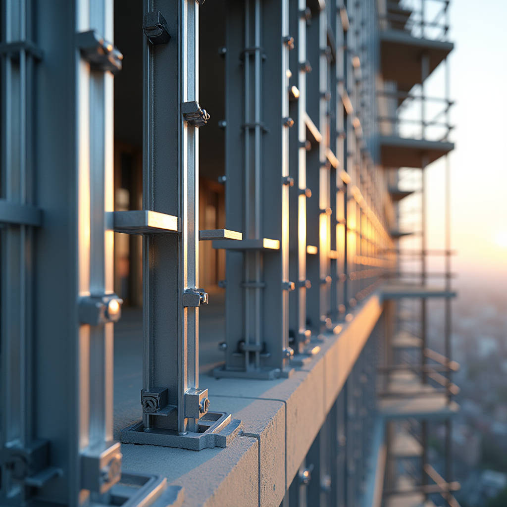
When a curtain wall contractor opens a shipment of solid aluminium cladding panels and finds the substructure components warped, undersized, or mismatched to the project's wind zone, the entire installation schedule collapses. The Aluminum Carrier Profile—the vertical or horizontal load-bearing extrusion that transfers dead loads and wind suction forces from the cladding face to the building's primary structure—is not a commodity accessory. It is a precision-engineered structural element that determines whether a ventilated rainscreen facade performs as calculated for 30 years or develops fatigue cracks in the first seasonal storm cycle. This article examines the structural mechanics, alloy selection, connection detailing, and thermal movement accommodation that separate a properly specified Aluminum Carrier Profile from a site-level failure waiting to happen.
What an Aluminum Carrier Profile Actually Does in a Rainscreen System
In a drained and ventilated rainscreen assembly, the outer solid aluminium cladding panel—typically 2.5 mm or 3.0 mm thick with a PVDF coating of 28–35 microns—is not directly bonded to the weather barrier. It hangs on a grid of carrier profiles. These extrusions, usually T-shaped, L-shaped, or hat-shaped in cross-section, span between structural brackets anchored to the floor slab or steel framing. The Aluminum Carrier Profile performs three distinct mechanical functions simultaneously.
First, it carries the self-weight of the cladding panel. A 3.0 mm solid aluminium sheet measuring 1,500 mm × 3,000 mm weighs approximately 36 kg. Multiply that across a 20-storey elevation and the cumulative dead load on the lowest row of carrier profiles reaches several tonnes. Second, the profile resists wind suction—the negative pressure that tries to pull the panel away from the building. In coastal high-rise applications, design wind loads routinely exceed 2.5 kPa, and the carrier profile's section modulus must be calculated to keep deflection under L/175, as required by AAMA 508. Third, the profile must accommodate differential thermal movement between the aluminium skin (which expands at roughly 2.4 mm per linear metre across a 100°C surface temperature swing) and the steel or concrete substrate behind it.
A profile that handles dead load but buckles under negative wind pressure, or one that is rigid enough for wind but traps thermal stress, will fail. The engineering challenge is balancing all three demands within a single extrusion geometry.
Alloy Selection: Why 6063-T6 and 6005A-T6 Dominate Facade Carrier Profiles
The Aluminum Carrier Profile is almost always extruded from 6xxx-series heat-treatable alloys. The two workhorses are 6063-T6 and 6005A-T6, and the choice between them has measurable consequences for load tables, weldability, and cost.
6063-T6 offers an ultimate tensile strength of approximately 215 MPa and yield strength around 170 MPa. It extrudes easily, accepts anodising uniformly, and is the default choice for moderate-span applications—window wall mullions, low-rise rainscreen grids, and interior carrier profiles where spans stay under 3.0 metres. It is also the more economical option, with raw billet costs typically 5–8% lower than 6005A.
6005A-T6 delivers roughly 260 MPa tensile and 215 MPa yield—a 25% strength advantage over 6063-T6. This makes it the preferred alloy for wide-span carrier profiles (4.0–6.0 metres between bracket points), high-wind-zone facades, and projects where the architect wants to minimise the visible profile depth. The trade-off is extrusion speed: 6005A runs slower through the die, increasing per-metre extrusion cost. It also requires tighter quench control at the press to achieve consistent T6 properties across the profile wall thickness.
For projects in marine environments, some specifiers push for 6082-T6 (yield ~250 MPa) due to its marginally better corrosion resistance, but the extrusion complexity and cost penalty usually push the decision back to 6005A with a robust PVDF or polyester powder coating system. The key takeaway: alloy selection is not a purchasing decision. It is a structural engineering decision that must reference the project's specific span tables, wind tunnel data, and bracket spacing.
| Alloy & Temper | Tensile Strength (MPa) | Yield Strength (MPa) | Typical Span Range | Relative Cost Index | Best Application |
|---|---|---|---|---|---|
| 6063-T5 | 150 | 110 | ≤ 2.0 m | 0.85 | Interior trim, low-load soffits |
| 6063-T6 | 215 | 170 | 2.0–3.5 m | 1.00 | Standard rainscreen, window wall |
| 6005A-T6 | 260 | 215 | 3.5–6.0 m | 1.12 | High-wind, wide-span facades |
| 6082-T6 | 310 | 250 | 4.0–6.5 m | 1.25 | Marine, heavy structural grids |
Section Geometry and the Moment of Inertia Calculation
The structural performance of an Aluminum Carrier Profile is governed by its moment of inertia (I-value) about the axis perpendicular to the wind load. A T-profile with a 60 mm web and 80 mm flange might have an I-value of 180,000 mm⁴ in the strong axis. The same profile rotated 90 degrees—or a flat bar of equivalent mass—might have an I-value under 15,000 mm⁴. The difference in deflection under identical load is an order of magnitude.
This is why carrier profiles for solid aluminium cladding panels are almost always oriented with the web perpendicular to the building face. The flange provides the attachment surface for the panel clips or rivets; the web provides the depth that generates stiffness. A 3.0 mm panel with a 1.5 m² face area, subjected to a 2.0 kPa wind suction load, generates approximately 3.0 kN of force distributed across its carrier profile connections. If the profile deflects more than span/175 (roughly 17 mm over a 3.0 m span), the panel joints will open, gaskets will disengage, and water ingress becomes inevitable.
Experienced facade engineers run these calculations early in the design phase. They specify the profile depth, web thickness, and flange width not by catalogue selection but by back-calculating from the required I-value. A 2.0 mm web thickness might be adequate for a 2.5 m span in a low-wind zone; the same profile in a typhoon-prone region might need a 3.0 mm web. The mass penalty is real—roughly 0.8 kg per linear metre per millimetre of added web thickness—but the alternative is a profile that fails the deflection check.
For projects where the architect demands a slim sightline, suppliers like Futeng® can provide custom-extruded carrier profiles with internal stiffening ribs that boost the I-value without increasing the visible flange width. This approach requires die investment but often pays for itself in reduced bracket count and faster installation.
Connection Design: Brackets, Thermal Breaks, and the Fixing Point
The interface between the Aluminum Carrier Profile and the primary structure is where most system failures originate. A carrier profile can be perfectly engineered in isolation, but if the bracket connection does not allow for vertical slotted adjustment, thermal expansion, and construction tolerance, the system will lock up and buckle.
Three connection principles govern reliable carrier profile detailing:
Fixed Point vs. Sliding Point
Every carrier profile run needs one fixed-point bracket that resists vertical and horizontal movement. All other brackets along the same run must be sliding points—typically slotted vertically to allow the profile to expand and contract freely. A 4.0-metre 6063-T6 carrier profile subjected to a 70°C temperature delta will grow by approximately 6.5 mm. If both ends are fixed, that 6.5 mm manifests as compressive stress in the profile, which can cause lateral buckling between bracket points. The rule: one fixed point per continuous run, sliding points elsewhere.
Thermal Break Integration
In cold climates, a steel bracket bolted directly to an aluminium carrier profile creates a thermal bridge that can drop the internal surface temperature of the mullion below the dew point. The result is condensation inside the facade cavity, which corrodes fixings and saturates insulation. A 6–10 mm polyamide or PVC thermal break pad between the bracket and the carrier profile solves this. The thermal break must be structurally rated—not just a gasket—and the bolt torque must be calculated to account for the creep behaviour of the polymer under sustained compression.
Bracket Material Compatibility
Aluminium carrier profiles bolted to galvanised steel brackets create a galvanic couple in the presence of moisture. The aluminium acts as the anode and corrodes preferentially. The standard mitigation is a separation layer: either an EPDM gasket, a nylon washer at every bolt, or a full polyamide bracket. In C4 and C5 corrosion environments (coastal, industrial), stainless steel brackets (grade 316) are specified instead of galvanised steel, eliminating the galvanic mismatch entirely. The cost uplift is approximately 30–40% for bracket material, but the alternative—carrier profile replacement within 10 years—is far more expensive.
Wind Load Deflection and the L/175 Standard
The Aluminum Carrier Profile must satisfy two deflection criteria under design wind load: strength (it must not yield) and serviceability (it must not deflect so much that the cladding panel joints open). AAMA 508 and the AAMA TIR-A11 technical report specify L/175 as the maximum allowable deflection for cladding support components under wind load, where L is the span between bracket points. Some European standards, such as EN 13830, tighten this to L/200 for curtain wall mullions.
A practical calculation illustrates the stakes. Consider a 6005A-T6 Aluminum Carrier Profile with an I-value of 250,000 mm⁴, spanning 4.0 metres between brackets, carrying a tributary wind load width of 1.2 metres, at a design wind pressure of 2.2 kPa. The uniformly distributed load is 2.64 kN/m. The maximum deflection for a simply supported beam under UDL is:
δ_max = (5 × w × L⁴) / (384 × E × I) = (5 × 2.64 × 4.0⁴) / (384 × 69,000 × 250,000 × 10⁻⁹) ≈ 12.7 mm
L/175 for a 4.0 m span is 22.9 mm, so the profile passes comfortably. If the same profile were specified in 6063-T6 with a thinner web (I = 180,000 mm⁴), the deflection jumps to approximately 17.6 mm—still passing but with less margin. If the architect then changes the bracket spacing to 5.0 metres, the deflection under 6063-T6 reaches 34.5 mm, exceeding L/175 and requiring either a profile upgrade or additional brackets. This is the type of cascade effect that catches out under-resourced design teams.
Corrosion Protection and Coating Synergy
An Aluminum Carrier Profile is typically hidden behind the cladding panel, but it is not protected from the cavity environment. Rainwater driven through open joints, condensation, and airborne chlorides all circulate in the ventilated cavity. The carrier profile needs its own corrosion protection, independent of the visible panel finish.
For most urban and suburban projects, a 60-micron polyester powder coating applied to the carrier profile after cutting and drilling provides adequate protection. The powder coating seals the cut edges where the aluminium is most vulnerable to pitting. For coastal projects within 5 km of breaking surf, a 40-micron minimum PVDF coating—or, more commonly, a 15-micron anodised layer to AA20 specification—is specified. Anodising grows an aluminium oxide layer that is integral to the metal surface, so it cannot delaminate like a paint film. The trade-off is that anodising does not cover weld zones uniformly, so welded carrier profile assemblies are typically powder coated instead.
One detail that is frequently missed: the carrier profile's cut ends, where the extrusion is sawn to length on site, must be treated with a cold-applied zinc chromate primer or an equivalent touch-up coating. Unprotected cut ends in a marine cavity environment will show white corrosion product within 6–12 months. This is a site QA/QC item that the facade consultant should flag in the inspection and test plan.
Thermal Movement: Designing the Joint That Moves
Aluminium expands and contracts at approximately 23.4 × 10⁻⁶ per degree Celsius. A 5.0-metre Aluminum Carrier Profile on a dark-coloured facade in the Middle East can experience a surface temperature swing from 15°C at night to 85°C under direct sun—a delta of 70°C. The linear expansion is:
ΔL = 23.4 × 10⁻⁶ × 5,000 mm × 70 = 8.2 mm
That 8.2 mm must go somewhere. If the carrier profile is rigidly fixed at both ends, the compressive stress in the aluminium reaches approximately 130 MPa—approaching the yield strength of 6063-T6. The profile will buckle laterally between restraints, pushing the cladding panels outward and creating uneven joint lines.
The solution is an expansion joint in the carrier profile grid at intervals of 8–12 metres, depending on the expected temperature range. At each expansion joint, the carrier profile is cut and a sliding sleeve—typically a short section of the same profile with a slightly smaller section that telescopes inside—bridges the gap. The sleeve is fixed to one side and free to slide on the other, maintaining structural continuity across the joint while allowing axial movement. The cladding panel joint above the expansion gap is filled with a silicone sealant capable of ±25% movement accommodation.
Installation Tolerance and the Carrier Profile Alignment Problem
The best-engineered Aluminum Carrier Profile performs poorly if the primary structure is out of tolerance. Concrete floor slabs routinely deviate ±15 mm from the theoretical plane. Steel framing can be out by ±10 mm. If the carrier profile brackets are fixed directly to the slab edge without adjustment capability, the profile grid will follow every deviation, and the cladding panel joints will be visibly uneven.
The standard fix is a three-axis adjustable bracket system. The bracket base is anchored to the slab with a cast-in channel or post-installed anchor, allowing ±20 mm of horizontal adjustment. A vertical slotted connection between the bracket and the carrier profile provides ±15 mm of vertical adjustment. The third axis—in/out from the building face—is handled by shims or a threaded rod adjustment on the bracket arm, typically providing ±25 mm of adjustment. This three-axis system allows the installer to establish a perfectly planar carrier profile grid regardless of substrate irregularities.
Surveying the installed carrier profiles with a total station before panel installation is a recommended QA step. A tolerance of ±2 mm across a 10-metre grid is achievable with careful bracketry and is tight enough that 3.0 mm solid aluminium panels will show uniform 8–10 mm shadow gaps.
Fire Performance and the Carrier Profile's Role in Cavity Barriers
Aluminium melts at approximately 660°C. In a fully developed facade fire, the Aluminum Carrier Profile will lose structural integrity unless it is protected by cavity fire barriers. The carrier profile itself is not a fire-rated component, but its geometry and spacing directly affect the design of horizontal and vertical cavity barriers.
Building codes such as the International Building Code (IBC) Section 715 and NFPA 285 require cavity barriers at each floor level and at vertical intervals not exceeding 10 metres. These barriers—typically intumescent strips or mineral wool with a foil facing—must span the full cavity depth between the weather barrier and the back face of the cladding panel. The carrier profile's web depth and flange width define the cavity width, so the fire engineer must have the finalised carrier profile shop drawings before specifying the cavity barrier dimensions.
In projects where the carrier profile spacing exceeds 600 mm centres, additional vertical fire stops may be required to prevent the cavity from acting as a chimney. This is a coordination item that the facade contractor should raise during the shop drawing review, not after the profiles are installed.
Cost Drivers and the Value of Early-Stage Engineering
The Aluminum Carrier Profile typically accounts for 12–18% of the total rainscreen facade material cost, but its influence on installation labour is disproportionate. A well-designed carrier profile with pre-punched fixing slots, integrated clip grooves, and clear alignment marks can be installed at 15–20 linear metres per installer per hour. A generic profile that requires on-site drilling, shimming, and improvisation might achieve 5–8 metres per hour. Over a 10,000 m² facade, the labour cost difference can exceed USD 50,000.
The cost drivers for carrier profiles, in order of impact, are: alloy choice (6005A vs. 6063), profile mass per metre (driven by web and flange thickness), coating specification (powder vs. anodised), bracket complexity (three-axis adjustable vs. simple L-bracket), and the degree of prefabrication (pre-cut and pre-punched vs. stock lengths cut on site). The cheapest per-metre extrusion price rarely yields the lowest installed cost.
For international projects, sourcing the Aluminum Carrier Profile from a supplier that can provide both the extrusion and the matching bracket system eliminates the finger-pointing that occurs when the profile comes from one factory and the brackets from another. Integrated supply chains reduce tolerance stack-up and simplify warranty claims. This is a practical consideration that experienced project managers factor into procurement decisions early in the programme.
Specifying the Aluminum Carrier Profile: A Practical Checklist
Based on the structural, thermal, and installation factors discussed, a robust specification for an Aluminum Carrier Profile in a solid aluminium rainscreen system should address the following points:
- Alloy and temper: Specify 6063-T6 or 6005A-T6 per structural calculations, referencing EN 755-2 or ASTM B221.
- Section properties: Provide minimum I-value and section modulus for the strong axis, not just the profile dimensions.
- Coating: Define the coating type (polyester powder, PVDF, or anodised), minimum thickness, and applicable standard (Qualicoat, AAMA 2604/2605, or BS 3987 for anodising).
- Bracket system: Require three-axis adjustability, thermal break pads where climate demands, and stainless steel fixings in corrosive environments.
- Expansion joints: Detail the location, sleeve design, and sealant specification for movement joints at 8–12 metre intervals.
- Deflection limit: State L/175 under design wind load per AAMA TIR-A11, or L/200 if adopting the more conservative EN 13830 approach.
- QA/QC: Mandate cut-end treatment, total station survey of installed grid, and pull-out testing of anchors per AAMA guidelines.
This checklist, when embedded in the project specification, gives the facade contractor clear performance criteria and eliminates the ambiguity that leads to value-engineered substitutions with inadequate section properties.
The Aluminum Carrier Profile is the skeleton of the rainscreen facade. It carries the weight, resists the wind, absorbs the thermal movement, and defines the cavity geometry that makes the system drain and dry. Specifying it correctly—starting from the alloy and section modulus, through the bracket connection details, to the site installation tolerances—is not a secondary task. It is the structural logic that determines whether the cladding panels on the outside look straight, stay straight, and perform as designed for the building's service life. When the engineering is done right, the carrier profile is invisible. When it is done wrong, every panel joint tells the story.