Aluminum Rail System Integration with Solid Cladding Engineering the Guardrail to Facade Connection
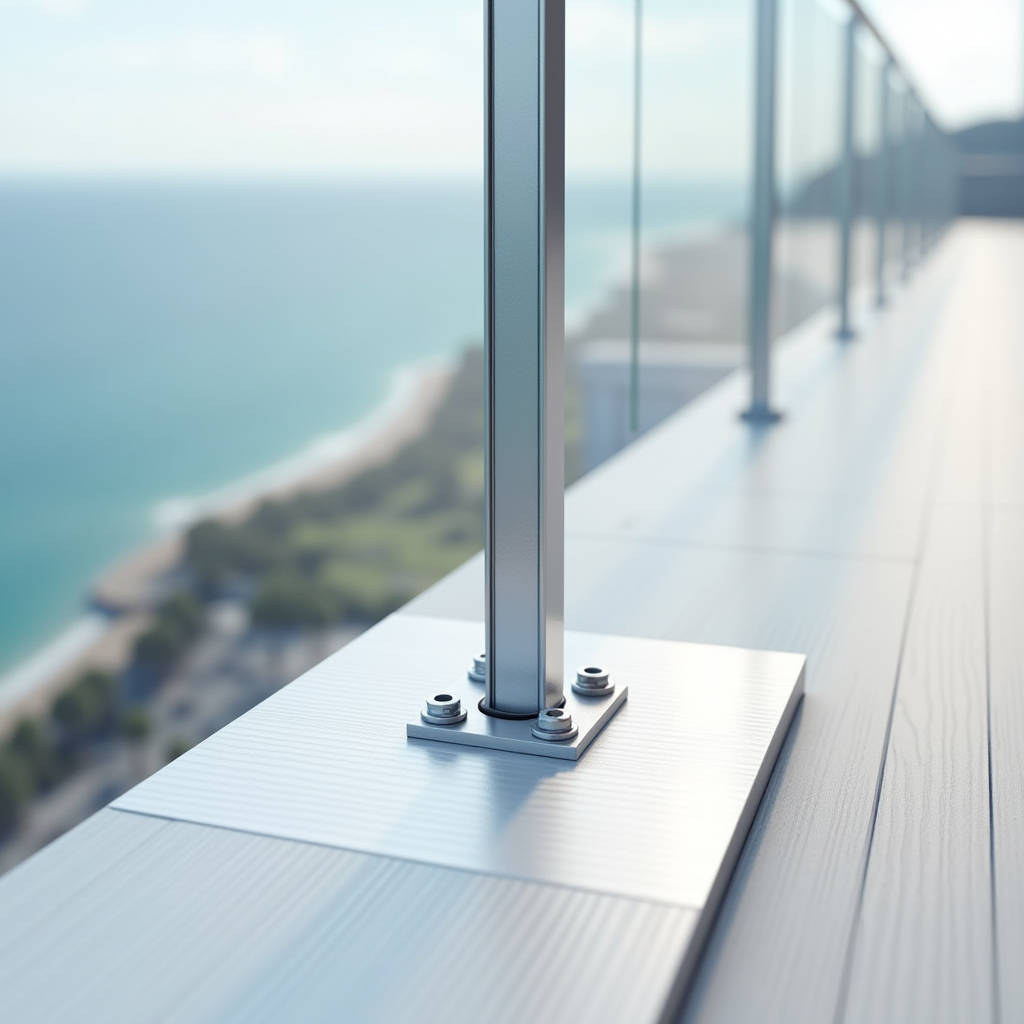
When a facade contractor evaluates railing integration with a building envelope, the conversation rarely starts with the railing itself. It starts with the joint. The interface where an Aluminum Rail System meets the cladding substrate determines whether the assembly performs for 20 years or leaks after two seasons. This article examines that critical connection point from the perspective of solid aluminum cladding engineering, focusing on structural load transfer, thermal movement accommodation, and water management at the guardrail-to-facade junction. Architects and general contractors who specify both cladding and railings as separate packages often discover too late that the two systems were never designed to work together. The result is site-drilled anchors, compromised weather barriers, and warranty disputes that no one wants to own.
Why the Cladding-to-Railing Interface Fails First
Building envelope failures follow a predictable pattern. They concentrate at penetrations. An Aluminum Rail System mounted on a terrace, balcony, or rooftop plaza creates dozens of penetrations through the cladding and weather barrier. Each anchor point represents a potential water entry path. When the cladding is solid aluminum panels at 2.5mm or 3.0mm thickness with a PVDF coating system, the material itself is not the weak link. The problem is almost always the detailing of the penetration and the sequencing of installation.
Most specifications treat the railing as Division 05 and the cladding as Division 07. The submittal review process checks each system independently for code compliance. The railing engineer verifies that the post can resist the 200-pound concentrated load required by IBC 1607.8.1. The cladding engineer confirms the panel can span between its girts and handle wind loads per ASCE 7. Nobody checks what happens when the post base plate bears directly on the aluminum panel surface.
A solid aluminum panel at 3.0mm with a 5052-H32 temper has a yield strength around 193 MPa. That sounds substantial until you calculate the bearing stress under a 100mm x 100mm base plate subjected to a 0.9 kN design moment at the post base. The panel will deflect locally. Over time, this cyclic loading from wind and human contact loosens the anchor. Water finds the gap. The fix is not thicker panels. The fix is a sub-frame that transfers rail loads directly to the structural backup, bypassing the cladding entirely.
Load Path Engineering for Guardrail Anchorage
The core principle is straightforward: an Aluminum Rail System must never rely on the cladding panel as a structural element. The load path runs from the handrail through the post, into the base plate, through the anchor bolts, and into the building structure. The cladding is simply in the way. The engineering challenge is designing a penetration detail that maintains this load path while preserving the water and air barrier continuity.
Three common approaches exist in current practice, each with different cost and performance profiles:
- Through-post mounting: The railing post extends through a sleeved opening in the cladding and anchors directly to the structural slab edge or steel beam. The sleeve is welded to the post and flashed to the cladding weather barrier. This is the most reliable method but requires precise coordination between the railing installer and the cladding contractor.
- Surface-mounted with internal blocking: A reinforced backing plate or steel channel is installed behind the cladding panel, aligned with the post positions. The post base bolts pass through the cladding and thread into the blocking. The cladding panel is clamped between the base plate and the blocking, but the structural load bypasses the aluminum skin.
- Curb-mounted with integrated flashing: A raised concrete or steel curb is waterproofed independently, and the railing posts are anchored to the top of the curb. The cladding wraps the vertical face of the curb and terminates under a metal coping. This approach keeps all penetrations above the drainage plane.
The curb-mounted approach has gained traction in high-rise residential projects across Southeast Asia and the Middle East, where solid aluminum cladding panels from manufacturers like Futeng® are often specified alongside integrated balcony railings. The curb creates a natural separation between the horizontal walking surface waterproofing and the vertical cladding system, simplifying the interface detailing for both trades.
Thermal Movement: The Overlooked Stressor
Aluminum expands at roughly 0.000023 mm per mm per degree Celsius. A 3-meter-long solid aluminum panel subjected to a 60°C temperature swing (from -10°C winter night to 50°C summer sun exposure) will move approximately 4.1mm. An Aluminum Rail System post anchored rigidly through such a panel creates a fixed point that resists this movement. The resulting stress concentrates at the penetration.
The math is worth examining. For a 5052-H32 aluminum panel at 2.5mm thickness, the cross-sectional area resisting thermal expansion is 2,500 mm² per meter of panel width. The thermal strain over 60°C is 0.00138. The corresponding stress if fully restrained would be approximately 96 MPa, which is roughly half the yield strength. This is not an immediate failure condition, but combined with wind cycling and anchor point stress concentrations, fatigue cracking can initiate within 5-10 years in high-cycle locations.
The practical solution is not to eliminate restraint but to accommodate movement through detailing. Oversized holes with neoprene grommets at the post base connections allow the panel to move independently of the fixed railing post. The grommet also serves as a secondary seal at the penetration. The hole diameter should be calculated as:
D_hole = D_bolt + (α × L × ΔT) + 3mm clearance
Where α is the thermal expansion coefficient, L is the distance from the panel's fixed point to the penetration, and ΔT is the design temperature range. For most applications, a 2mm to 4mm oversize relative to the bolt diameter is adequate, but the exact value should be confirmed by the project's facade engineer based on local climate data.
Water Management at the Penetration: A Three-Layer Strategy
Water that reaches the cladding surface at a railing post penetration has three potential paths: it can drain down the face of the panel, it can enter the penetration, or it can track horizontally along the post and enter at the base plate joint. A competent detail addresses all three paths simultaneously.
The industry standard approach follows the rainscreen principle adapted for penetrations. The outer layer is the exposed post base cover or escutcheon plate, which sheds the majority of incident water. The middle layer is a compressible EPDM gasket compressed between the base plate and the panel surface, forming the primary seal. The inner layer is the weather barrier continuity at the penetration, typically achieved with a liquid-applied flashing that bonds to both the panel substrate and the anchor sleeve.
Testing standards provide a framework for verifying performance. ASTM E1105 measures water penetration resistance under a static pressure differential. AAMA 501.1 applies a dynamic pressure with cyclic loading. For balcony and terrace applications where an Aluminum Rail System penetrates the cladding, the assembly should be tested to at least 300 Pa (6.27 psf) without water ingress, which corresponds to a wind-driven rain condition at approximately 80 km/h.
The table below summarizes the key performance criteria for different sealant and gasket materials commonly used at railing-to-cladding penetrations:
| Material | Movement Capability | Service Temperature Range | Expected Service Life | Relative Cost per Linear Meter |
|---|---|---|---|---|
| Silicone Sealant (Neutral Cure) | ±50% | -55°C to 200°C | 20-30 years | $3.50 - $6.00 |
| Polyurethane Sealant | ±25% | -40°C to 90°C | 15-20 years | $2.80 - $4.50 |
| EPDM Compression Gasket | ±30% (compression) | -50°C to 120°C | 25+ years | $4.00 - $8.00 |
| Silicone Preformed Gasket | ±40% (compression) | -60°C to 200°C | 30+ years | $5.50 - $10.00 |
| Butyl Tape (Non-curing) | ±10% | -30°C to 70°C | 10-15 years | $1.50 - $3.00 |
EPDM compression gaskets paired with a silicone secondary seal consistently deliver the best long-term performance for solid aluminum cladding applications. The gasket handles the dynamic movement while the silicone provides the weathertight backup. This combination is specified in projects ranging from Gulf Coast condominiums to Scandinavian winter sports facilities, where thermal cycling is extreme and maintenance access is limited.
Galvanic Corrosion: The Hidden Risk at the Bracket
An Aluminum Rail System typically uses aluminum posts and rails. The cladding panels are aluminum. The backup structure is often galvanized steel or stainless steel. The anchor bolts might be stainless steel. This mix of metals in the presence of an electrolyte (rainwater, coastal spray) creates a galvanic cell. Aluminum is anodic relative to steel and stainless steel, meaning the aluminum will corrode sacrificially to protect the more noble metals.
The galvanic series in seawater puts aluminum 5052 at approximately -0.76V relative to a saturated calomel electrode, while 304 stainless steel sits at around -0.05V. The potential difference of 0.71V is sufficient to drive significant corrosion if the metals are in direct electrical contact and wetted. The corrosion rate depends on the relative surface areas. A small stainless steel bolt in a large aluminum panel creates a favorable ratio where the aluminum corrodes slowly. A large steel backup angle in contact with a small aluminum bracket creates an unfavorable ratio that can lead to rapid bracket failure.
The mitigation strategy follows three principles:
- Physical separation: Insert a non-conductive isolator between dissimilar metals. A 0.5mm PTFE or nylon washer at every bolt connection breaks the electrical path. The cost is negligible compared to the cost of replacing corroded anchors.
- Drainage design: Eliminate water traps at the connection. A sloped base plate surface with a drip edge detail prevents standing water from maintaining the electrolyte bridge.
- Coating continuity: Ensure that PVDF or anodized finishes extend fully around all cut edges and drilled holes. Field-drilled holes in factory-finished panels expose bare aluminum and create localized corrosion cells. Touch-up pens are not adequate for long-term protection. The hole should be pre-drilled in the factory and the cut edge coated before the panel leaves the production line.
For projects within 5 kilometers of a marine coastline, the requirements tighten. AAMA 2605-compliant PVDF coatings with a minimum 30-micron dry film thickness provide a robust barrier, but the real protection comes from the chrome-based pretreatment under the coating. Specifying a minimum coating weight of 300 mg/m² for the chrome conversion layer is a practical benchmark that many facade consultants now include in their performance specifications.
Installation Sequencing and Trade Coordination
The most technically sound detail fails if the installation sequence does not allow it to be built correctly. The cladding contractor needs access to install the weather barrier before the railing contractor anchors the posts. The railing contractor needs the cladding in place to set the base plate elevations. These two requirements conflict, and the resolution depends on the chosen mounting method.
For through-post systems, the sequence typically runs:
- Structural backup and primary weather barrier installed by the general contractor
- Railing posts set and anchored, with sleeves and secondary flashing installed by the railing contractor
- Cladding panels installed around the posts, with the panel-to-sleeve joint sealed by the cladding contractor
- Post base covers and escutcheons installed by the railing contractor as final trim
This sequence requires the railing contractor to mobilize twice, which adds cost. The alternative is a surface-mounted system with pre-installed blocking, where the cladding goes up first, the railing contractor arrives once, and the posts bolt through to the pre-positioned blocking. The trade-off is that the blocking positions must be accurate to within 5mm in both plan and elevation, which demands a higher level of survey and layout control during the backup framing phase.
Coordination drawings are not optional. A single drawing that shows the cladding panel layout superimposed on the railing post layout, with dimensions referenced to a common grid, eliminates the finger-pointing that occurs when post positions conflict with panel joints. The drawing should be produced by the facade consultant or the design-assist contractor, not left to the individual trades to resolve in the field.
Testing and Verification Protocols
Mock-up testing is the only reliable way to validate a cladding-to-railing interface detail before production quantities are fabricated. The mock-up should include at least two full cladding panels with one railing post penetration at the panel joint and one penetration in the field of the panel. This configuration tests both the edge condition and the mid-panel condition simultaneously.
The testing sequence recommended by the American Architectural Manufacturers Association (AAMA) includes:
- Air infiltration testing per ASTM E283 at 300 Pa differential pressure
- Static water penetration testing per ASTM E1105 at 300 Pa
- Dynamic water penetration testing per AAMA 501.1 at 300 Pa with cyclic pressure
- Structural load testing of the railing per IBC 1607.8.1 (200 lb concentrated load at mid-span of top rail in any direction)
- Post-test disassembly to inspect for hidden water tracks, sealant adhesion failure, or corrosion initiation
The post-test disassembly is the step that many project teams skip to save time, and it is the step that reveals the most. A mock-up that passes the water test may still show moisture staining on the back side of the weather barrier, indicating that water is entering but not yet reaching the interior. That condition will deteriorate over time. Finding it at the mock-up stage allows the detail to be refined before 500 identical penetrations are built on the tower.
Specifying the Right Aluminum Rail System for Solid Cladding Projects
Not all aluminum railing products are equally suited to integration with solid aluminum cladding. The key specification criteria that matter at the interface include:
- Base plate geometry: A base plate with a raised central boss and a continuous perimeter bearing surface provides better load distribution and seal compression than a flat plate. The raised boss creates a standoff that allows water to drain behind the plate rather than pooling at the seal.
- Alloy compatibility: The railing alloy should be within 100mV of the cladding alloy on the galvanic series to minimize corrosion potential. 6063-T6 railing components paired with 5052-H32 cladding panels fall within an acceptable range for most environments.
- Finish system: The railing finish should match or exceed the durability of the cladding finish. AAMA 2604 powder coating on railings paired with AAMA 2605 PVDF on cladding creates a mismatch where the railing finish degrades faster. Specifying AAMA 2605 for both systems, or at minimum a high-durability polyester powder coating meeting Qualicoat Class 2, ensures consistent appearance over the building's service life.
When an Aluminum Rail System is procured as part of a complete facade package that includes solid aluminum cladding, the interface detailing becomes the responsibility of a single entity. This integrated approach, which manufacturers like Futeng® facilitate by coordinating both the cladding panel production and the railing interface engineering, eliminates the coordination gap that plagues separately procured systems. The cost premium for integrated procurement is typically offset by reduced site labor for remedial work and fewer warranty claims during the defects liability period.
Cost Implications of Interface Detailing Choices
The cost of the railing-to-cladding interface is not the cost of the brackets and sealants. It is the cost of the coordination, the testing, and the risk allocation. A through-post system with sleeved penetrations might add $12 to $18 per linear meter of railing in material and fabrication costs compared to a simple surface-mounted detail. The coordination cost, however, can be $30 to $50 per meter if the trades are not aligned and rework is required.
Projects that invest in a pre-construction mock-up and coordinated shop drawings consistently report lower total installed costs than projects that attempt to resolve interface issues in the field. The mock-up cost of $8,000 to $15,000 for a typical balcony configuration is a fraction of the cost of stripping and replacing 50 linear meters of cladding to correct leaking penetrations after occupancy.
The value engineering conversation should focus on optimizing the mounting method and sealant specification, not on eliminating the interface detailing altogether. A $2 per meter saving on sealant specification that results in a $200 per meter remediation cost five years later is not value engineering. It is deferred maintenance masquerading as cost control.
Long-Term Performance and Maintenance Planning
A properly detailed Aluminum Rail System integrated with solid aluminum cladding should require minimal maintenance over a 30-year service life. The maintenance that is required should be planned and budgeted from day one. The operations and maintenance manual should include:
- Annual visual inspection of all penetration seals, with particular attention to south-facing and west-facing elevations where UV exposure is highest
- Cleaning of drainage paths and weep holes at post base details every 6 months in coastal environments to prevent salt buildup
- Re-torquing of accessible anchor bolts at year 5 and year 15, with documented torque values compared to the original installation records
- Sealant adhesion testing at year 10 using the ASTM C1521 pull-off method on a representative sample of joints
The building owner who understands these requirements at handover is far less likely to face unexpected failures. The facade contractor who provides clear maintenance documentation distinguishes their work from competitors who walk away after the defects period ends. In an industry where reputation travels through a small network of consultants and developers, the quality of the interface detailing becomes a calling card for future work.
The junction between an aluminum railing and a solid aluminum cladding panel is a detail that occupies perhaps 0.1% of the building's surface area. It demands a disproportionate share of engineering attention. Getting it right requires understanding load paths, thermal movement, water management, galvanic compatibility, and trade sequencing. The reward is a building envelope that performs quietly for decades. The alternative is a leak that no one wants to own.