Aluminum Extrusion Keel Load Path Design and Alloy Selection for Solid Cladding Facades
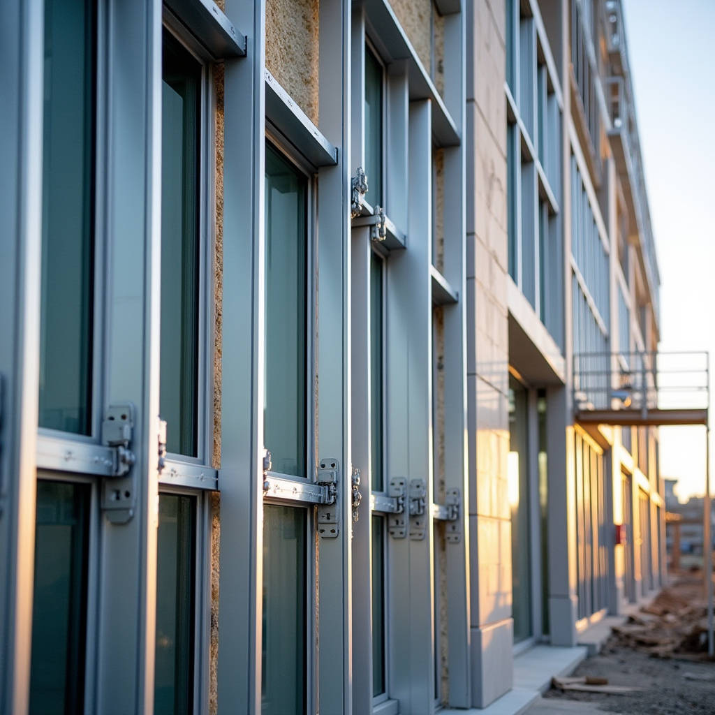
When a curtain wall contractor evaluates the structural backbone of a ventilated facade system, the conversation inevitably turns to the Aluminum Extrusion Keel. This component is not a decorative afterthought. It is the load-bearing skeleton that transfers wind pressure, dead weight, and thermal movement from the cladding surface back to the building substrate. Over the past decade, projects across the Middle East, Southeast Asia, and Northern Europe have pushed engineers to rethink how extruded aluminum subframes perform under extreme cyclic loading, corrosive coastal atmospheres, and increasingly stringent fire safety codes. The shift from traditional galvanized steel subframes to precision-engineered 6063-T6 and 6061-T6 aluminum extrusion keel profiles has been driven by one undeniable reality: a facade is only as durable as the grid that holds it in place. This article examines the structural logic, material selection, connection detailing, and long-term performance of aluminum extrusion keel systems when paired with solid aluminum cladding panels in high-rise and mid-rise commercial envelopes.
What Defines an Aluminum Extrusion Keel in Facade Engineering
An Aluminum Extrusion Keel in the context of rainscreen and curtain wall construction refers to the vertical and horizontal load-bearing profiles that form the substructure grid behind solid aluminum cladding panels. These are typically fabricated from 6063-T6 or 6061-T6 aluminum alloys, selected for their balance of extrudability, mechanical strength, and corrosion resistance. The keel system consists of vertical mullions, horizontal transoms, and specialized connectors that create a unified framing grid. Unlike marine keels that run longitudinally along a vessel's hull, the architectural keel functions as a series of parallel load paths that distribute facade loads across multiple anchor points.
The cross-sectional geometry of these extrusions is engineered with specific design intent. Open-back profiles allow for thermal expansion clearance, while closed-box sections provide higher torsional rigidity. Wall thickness typically ranges from 1.8mm to 3.5mm depending on span, wind load, and panel weight. For solid aluminum panels weighing approximately 8.5 kg/m² at 3.0mm thickness, the keel must support not only the dead load but also the suction and pressure forces that can exceed 2.5 kPa in typhoon-prone regions. The dimensional tolerance of extruded aluminum keels, governed by EN 755-9 standards, ensures that the assembled grid maintains a flatness deviation of less than L/1000, which is critical when installing large-format panels up to 1500mm in width.
Load Path Analysis: How the Keel Handles Wind, Dead Load, and Seismic Forces
Understanding the load path through an aluminum extrusion keel system starts with the cladding panel itself. Wind pressure acting on the facade surface is transferred through the panel's perimeter fixings into the horizontal transoms. From there, the load travels to the vertical mullions via mechanical connectors or welded joints, and finally into the building's primary structure through adjustable brackets. Each connection point in this chain introduces a potential failure mode if not properly designed.
For a typical 3.0mm solid aluminum panel measuring 1200mm x 2400mm, the dead load is approximately 24.5 kg per panel. When wind loads reach 2.0 kPa — common in coastal high-rise applications — the total design load per panel approaches 5.76 kN. The aluminum extrusion keel must resist this without exceeding a deflection limit of L/360 under serviceability conditions, as specified in AAMA TIR-A9. Engineers calculate the required section modulus of the keel profile based on the span between anchor points. A vertical mullion spanning 3000mm between floor slabs, subjected to a uniformly distributed wind load of 2.0 kPa at a tributary width of 1200mm, requires a minimum section modulus of approximately 18.5 cm³ when using 6063-T6 alloy with an allowable bending stress of 150 MPa.
Seismic considerations add another layer of complexity. The aluminum extrusion keel must accommodate inter-story drift without transferring excessive forces into the cladding panels. This is achieved through slotted connections at the mullion brackets that allow for differential movement in the plane of the facade. In seismic zones classified as SDC D or higher, the keel connection design must allow for a drift ratio of at least 0.025 times the story height, which for a 4000mm floor-to-floor height translates to 100mm of relative displacement.
Alloy Selection: 6063-T6 vs 6061-T6 vs 6005A-T6 for Keel Applications
The choice of aluminum alloy for extrusion keel profiles directly impacts structural performance, fabrication cost, and long-term durability. Three alloys dominate the architectural facade market, each with distinct characteristics that suit different project requirements.
| Property | 6063-T6 | 6061-T6 | 6005A-T6 |
|---|---|---|---|
| Yield Strength (MPa) | 170 | 240 | 215 |
| Ultimate Tensile Strength (MPa) | 215 | 260 | 255 |
| Elongation (%) | 8 | 8 | 8 |
| Extrudability Rating | Excellent | Good | Very Good |
| Corrosion Resistance | Excellent | Very Good | Excellent |
| Weldability | Good | Excellent | Excellent |
| Typical Application | Standard facade grids | High-load zones | Structural mullions |
| Relative Cost Factor | 1.0 | 1.25 | 1.15 |
6063-T6 remains the workhorse alloy for aluminum extrusion keel profiles in standard facade applications. Its superior extrudability allows manufacturers to produce complex hollow profiles with thin walls and intricate geometries that optimize the strength-to-weight ratio. The alloy's natural oxide layer provides inherent corrosion resistance, which can be further enhanced through anodizing or powder coating. For projects within 5 kilometers of marine coastlines, 6063-T6 with a minimum 20-micron anodized finish or 60-micron polyester powder coating provides adequate protection against chloride-induced pitting.
When project specifications demand higher load capacity — such as for blast-resistant facades or panels exceeding 4.0mm thickness — 6061-T6 becomes the preferred choice. Its 240 MPa yield strength allows for slimmer profile sections that achieve the same structural performance, reducing the overall aluminum tonnage. However, the trade-off is a higher extrusion cost and slightly reduced formability for complex shapes. 6005A-T6 occupies the middle ground, offering yield strength 26% higher than 6063-T6 while maintaining good extrudability. This alloy is increasingly specified for structural mullions in unitized curtain wall systems where the aluminum extrusion keel must span floor-to-floor without intermediate support.
Thermal Performance and Condensation Risk Management
Aluminum is an excellent thermal conductor, with a thermal conductivity of approximately 160 W/m·K. This property, while beneficial for heat dissipation in electronics, creates challenges in facade applications where thermal bridging through the aluminum extrusion keel can compromise the building envelope's overall U-value. A continuous aluminum keel that penetrates the insulation layer creates a direct thermal path from the cold exterior to the warm interior, potentially causing condensation on interior surfaces during winter conditions.
The solution lies in the integration of thermal breaks within the keel assembly. These are typically polyamide strips (PA66 GF25) mechanically crimped between the interior and exterior aluminum profiles. A properly designed thermal break can reduce the profile's thermal transmittance (Uf value) from above 6.0 W/m²·K for a non-thermally broken section to below 2.5 W/m²·K. The ISO 10211 standard provides the methodology for calculating thermal bridges and verifying that the internal surface temperature remains above the dew point under design conditions.
For ventilated rainscreen systems, the cavity between the insulation and the cladding panel provides a drainage and ventilation path that helps manage moisture. However, the aluminum extrusion keel brackets that penetrate this cavity must be detailed with care. Each bracket should incorporate a thermal isolation pad, typically 5mm thick EPDM or neoprene, placed between the bracket and the structural substrate. The point thermal transmittance of these brackets, calculated as a Chi-value in W/K, should be verified through 3D thermal modeling for projects targeting Passive House or LEED certification.
Corrosion Protection Strategies for Coastal and Industrial Environments
While aluminum naturally forms a protective oxide layer, this passive film can break down under aggressive environmental conditions. Chloride ions from marine atmospheres and sulfur dioxide from industrial emissions are the primary culprits. The aluminum extrusion keel, being partially shielded behind the cladding but still exposed to cavity airflow, requires a corrosion protection strategy matched to the environmental severity classification defined in ISO 12944-2.
For C3 (medium) environments, a 15-micron chromate conversion coating followed by a 60-micron polyester powder coat provides 15-20 years of service life. For C4 (high) environments — typical of coastal industrial zones — the specification should upgrade to a 20-micron anodized finish (AA15 grade per AAMA 611) or a 80-micron fluoropolymer coating system. The anodizing process creates a thicker, more uniform oxide layer that is integral to the aluminum surface, while fluoropolymer coatings provide superior chemical resistance.
Galvanic corrosion is a separate concern that arises when the aluminum extrusion keel comes into contact with dissimilar metals in the presence of an electrolyte. Stainless steel fasteners (A2 or A4 grade) are generally compatible with aluminum, but carbon steel bolts will cause rapid galvanic attack. The bracket-to-substrate connection often involves a steel anchor embedded in concrete, and this interface must be isolated with a non-conductive gasket or bushing. In projects where Futeng® has supplied complete facade packages, the specification of 316-grade stainless steel hardware with nylon isolation sleeves has proven effective in preventing galvanic corrosion between the aluminum keel and structural steel supports.
Fabrication Tolerances and On-Site Assembly Challenges
The precision of an aluminum extrusion keel system begins at the extrusion die. Modern porthole dies can produce profiles with dimensional tolerances of ±0.15mm for critical functional dimensions such as screw ports and gasket grooves. However, the as-extruded straightness tolerance of ±1mm per meter requires careful handling during cutting, machining, and assembly. A 6000mm mullion with a 3mm bow over its length will create visible misalignment in the panel joints that cannot be corrected by the panel fixings alone.
On-site assembly introduces additional variables. The primary structure's as-built tolerances — typically ±25mm in plan position and ±15mm in level for concrete frames — must be absorbed by the adjustable bracket system. Three-dimensional adjustment capability (vertical, horizontal, and in-out) is essential. The bracket design should provide at least ±30mm of adjustment in each direction to accommodate structural deviations while maintaining the keel grid within the ±2mm tolerance required for panel installation.
Thermal expansion must also be accounted for in the assembly sequence. An aluminum extrusion keel profile will expand by approximately 1.2mm per meter over a 50°C temperature range. For a 4000mm mullion, this represents 4.8mm of thermal movement. Expansion joints at 10-15 meter intervals, or at building movement joints, prevent the accumulation of thermal stresses. The joint detail typically incorporates a sliding sleeve that maintains alignment while allowing axial movement, with a minimum 10mm gap between adjacent keel sections.
Cost Comparison: Aluminum Extrusion Keel vs. Alternative Subframe Materials
Procurement managers evaluating subframe options weigh initial material cost against lifecycle performance and installation efficiency. The following comparison provides a realistic cost framework for a 1000m² ventilated facade project with a 3000mm vertical span and 1200mm horizontal module.
| Cost Factor | Aluminum Extrusion Keel (6063-T6) | Galvanized Steel Subframe | Stainless Steel Subframe (304) |
|---|---|---|---|
| Material Cost (USD/m² facade) | 18 - 25 | 12 - 16 | 35 - 50 |
| Weight per m² (kg) | 3.5 - 5.0 | 8.0 - 12.0 | 7.5 - 11.0 |
| Installation Labor (hrs/m²) | 0.8 - 1.2 | 1.0 - 1.5 | 1.0 - 1.4 |
| Corrosion Protection Required | Anodizing or powder coat | Hot-dip galvanizing + paint | Passivation only |
| Service Life (C4 environment) | 30 - 40 years | 15 - 25 years | 40+ years |
| Recyclability | 95%+ (closed loop) | 90% (downcycling common) | 95%+ |
| Thermal Break Integration | Standard (polyamide strip) | Requires separate insulator | Requires separate insulator |
The aluminum extrusion keel commands a material cost premium of approximately 50% over galvanized steel, but this gap narrows significantly when factoring in installation efficiency and corrosion protection. Aluminum's lower weight reduces handling costs and allows for faster installation cycles. The ability to integrate thermal breaks directly into the extrusion profile eliminates the need for separate insulating components, simplifying the assembly sequence. Over a 30-year building lifecycle, the total cost of ownership for an aluminum keel system in a C4 environment is typically 15-20% lower than galvanized steel due to reduced maintenance and replacement requirements.
Fire Performance and Code Compliance for Aluminum Keel Systems
Fire safety regulations for facade systems have tightened significantly following high-profile cladding fires globally. While aluminum itself is non-combustible (classified as A1 per EN 13501-1), the complete keel assembly includes components — thermal breaks, gaskets, and sealants — that may contribute to fire load. The aluminum extrusion keel must be evaluated as part of the complete facade system, not in isolation.
The critical fire performance criteria for aluminum keel systems include reaction to fire (EN 13501-1), fire resistance (EN 13501-2), and the system's behavior in a full-scale facade fire test (BS 8414 or NFPA 285). Aluminum melts at approximately 660°C, and in a fully developed fire, unprotected aluminum keels can lose structural integrity within 5-10 minutes. For buildings above 18 meters in many jurisdictions, the facade system must limit vertical flame spread and prevent the aluminum substructure from contributing to fire propagation.
Fire-resistant detailing for aluminum extrusion keel systems includes the installation of horizontal fire stops at each floor level, typically consisting of mineral wool insulation and intumescent strips that expand to seal the cavity when exposed to heat. Vertical fire barriers at 10-meter intervals prevent lateral flame spread within the ventilated cavity. The keel brackets should be designed with a fire-resistant anchor that maintains load-bearing capacity for the required fire resistance period, typically 60 or 90 minutes depending on building height and occupancy classification.
Quality Verification and Factory Production Control
Specifying an aluminum extrusion keel is only the first step; verifying that the delivered product meets the specification requires a structured quality assurance program. The extrusion process itself is governed by EN 755 for dimensional tolerances and EN 515 for temper designation. However, facade-specific requirements go beyond these baseline standards.
Key quality checks should include: dimensional verification of critical functional dimensions using calibrated gauges; tensile testing per EN 10002-1 to confirm yield strength and elongation meet the specified alloy and temper; coating thickness measurement using eddy current gauges (ISO 2360 for anodizing, ISO 2808 for organic coatings); and adhesion testing per ISO 2409 (cross-cut test) to verify coating integrity. For anodized finishes, the sealing quality should be verified through the dye spot test (ISO 2143) or admittance test (ISO 2931).
Factory production control (FPC) documentation should be maintained for each batch of extrusions, linking the material certificates to the specific project. This traceability is essential for demonstrating compliance with construction product regulations. The FPC system should include records of billet chemistry, extrusion parameters, aging cycle data, and coating process parameters. For projects requiring third-party verification, an independent inspection agency can witness the testing and review the FPC documentation before shipment.
A well-designed aluminum extrusion keel system treats every connection point as a deliberate engineering decision rather than a standard detail. The difference between a facade that performs for 30 years and one that requires remedial work after 10 years often lies in the specification of bracket isolation, thermal break continuity, and expansion joint placement.
Practical Specification Checklist for Project Teams
For architects and facade engineers preparing specifications for solid aluminum cladding projects, the following considerations should be addressed in the subframe section of the performance specification:
- Alloy and temper: Specify 6063-T6 for standard applications, 6061-T6 for high-load zones, with mill certificates required per EN 10204 Type 3.1
- Dimensional tolerances: Reference EN 755-9 for extruded profiles, with a straightness tolerance of 0.5mm per meter for visible mullions
- Corrosion protection: Match the coating specification to the environmental severity class per ISO 12944-2, with minimum anodizing thickness of AA15 for C4 environments
- Thermal break: Require polyamide strips (PA66 GF25) with a minimum 20mm width for thermally broken profiles, verified by thermal simulation report
- Bracket adjustment: Minimum ±30mm three-dimensional adjustment at each anchor point, with slotted holes for inter-story drift accommodation
- Fire stopping: Horizontal cavity barriers at each floor level, vertical barriers at 10m intervals, with fire test evidence for the complete system
- Galvanic isolation: Non-conductive gaskets at all aluminum-to-steel interfaces, with 316-grade stainless steel fasteners
- Expansion joints: Provision for thermal movement at 12m maximum intervals, with a minimum 10mm gap and sliding sleeve detail
The aluminum extrusion keel represents a significant portion of the total facade cost — typically 12-18% of the installed rainscreen system — and its performance directly affects the longevity and safety of the entire building envelope. Investing time in the specification phase to define these parameters pays dividends in reduced site queries, faster installation, and a facade that performs as intended throughout its design life. For project teams seeking technical support on keel profile selection and structural calculation, manufacturers with dedicated facade engineering departments can provide project-specific design assistance, including finite element analysis of complex connection details and thermal performance modeling.