Aluminum Panel Hook Engineering Load Paths Fabrication Tolerances and Long Term Facade Performance
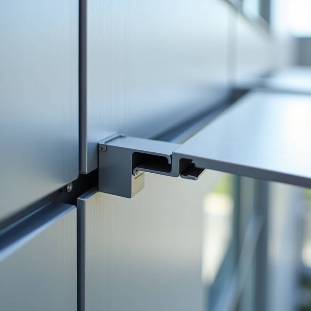
When a facade panel detaches at 40 stories, the failure rarely traces back to the sheet metal itself. It traces back to the connection. The Aluminum Panel Hook is that connection — a deceptively simple component that carries the full dead load of solid aluminium cladding panels while accommodating thermal movement, wind suction, and decades of exposure. For contractors and specifiers working with 2.0mm, 2.5mm, or 3.0mm solid aluminium sheets, the hook detail is not an afterthought. It is the difference between a facade that performs for 30 years and one that generates a call from the building owner in year three. This article examines the engineering logic behind hook-on panel systems, the material compatibility requirements, load path verification, and the practical installation factors that determine whether a hook detail succeeds or fails on site.
What a Hook Detail Actually Does in a Rainscreen Assembly
In a drained and ventilated rainscreen, the cladding panel does not seal the building. The air barrier behind it does. The panel deflects bulk water, controls the pressure equalization cavity, and carries wind loads back to the substructure. The Aluminum Panel Hook sits at the intersection of these functions.
A hook-on system typically involves a folded or extruded aluminium profile mechanically fixed to the rear face of the solid panel — either riveted, clinched, or welded at the fabricator's facility. This hook engages with a receiving rail or carrier profile anchored to the vertical mullions or horizontal girts of the curtain wall. The geometry of the hook determines how the panel hangs: some hooks are designed for bottom-up stacking, where each panel rests on the one below; others use individual hook-and-rail engagement at each panel perimeter.
The critical distinction is between load-bearing hooks and locating hooks. In a properly engineered system, the dead load of each panel is carried by dedicated load-bearing hooks at the top edge, while secondary hooks on the sides and bottom provide wind-load restraint and positional alignment. Mixing these functions — asking a side hook to carry gravity load — produces eccentric loading, rotation, and eventually, fatigue cracking at the fastener holes.
Material Selection: Why 6063-T6 and 5052-H32 Matter
Not all aluminium is equal when it comes to hook fabrication. The hook component experiences a combination of bearing stress at the rivet points, bending stress at the fold radius, and long-term creep under sustained dead load. Selecting the wrong alloy or temper leads to micro-cracking that propagates undetected behind the panel.
Extruded hooks are typically produced from 6063-T6, which offers a yield strength of approximately 170 MPa and good anodizing response. For folded hooks fabricated from sheet, 5052-H32 is the preferred choice — its higher magnesium content provides better fatigue resistance than 3003 or 1100 series alloys, and it accepts PVDF coating without adhesion issues. A 2.5mm solid aluminium panel with a 2.0mm-thick folded hook in 5052-H32 can reliably carry a panel measuring 1.2m x 3.6m, provided the hook engagement depth is at least 15mm and the fold radius is no tighter than 1.5 times the material thickness.
Galvanic corrosion is a persistent concern. When an Aluminum Panel Hook contacts a stainless steel receiving rail, the potential difference is small enough that isolation is not mandatory in most environments. However, if the rail is galvanized steel, a nylon or EPDM isolator strip between the hook and rail becomes essential. In coastal or industrial atmospheres, even aluminium-to-aluminium contact can trap moisture and initiate crevice corrosion. Specifying a minimum 60-micron PVDF coating on the hook itself — not just the visible panel face — closes this vulnerability.
Load Path Engineering: From Panel Face to Anchor
The load path for a hook-on panel deserves more scrutiny than it typically receives during shop drawing review. Wind pressure on the panel face transfers to the hook via the rivet or weld group, then from the hook to the rail, from the rail to the bracket, from the bracket to the anchor, and from the anchor into the substrate. Each interface introduces a potential failure mode.
Consider a 3.0mm solid aluminium panel measuring 1.5m wide by 4.0m tall, installed at a building corner where wind pressure reaches 2.5 kPa under the local code. The total wind force on the panel is 15 kN. Distributed across six hooks — three top, three bottom — each hook must resist 2.5 kN in tension or compression, depending on wind direction. The rivet group connecting the hook to the panel must handle this load plus the 0.45 kN dead load of the panel itself.
For a hook secured with four 4.8mm diameter aluminium blind rivets (typical for this application), the shear capacity per rivet is approximately 1.2 kN in 5052-H32 material. The four-rivet group provides 4.8 kN total shear capacity, yielding a utilization ratio of roughly 0.62 under the combined wind and dead load — acceptable by most international standards. Reducing the rivet count to three pushes utilization above 0.80, which leaves insufficient margin for installation tolerances and long-term degradation.
AAMA 508 provides a useful reference for testing these connections. The standard requires that panel attachment systems withstand 1.5 times the design load without permanent deformation exceeding 1.6mm. Hook systems that pass this test under cyclic loading — 50 cycles of positive and negative pressure — demonstrate the robustness needed for high-rise applications.
Thermal Movement: The Hidden Design Parameter
Solid aluminium expands and contracts at approximately 0.024mm per meter per degree Celsius. A 4-meter panel subjected to a 60°C temperature swing — from a winter night low of -10°C to a summer afternoon surface temperature of 50°C under direct sun — moves 5.76mm. If the hook system does not accommodate this movement, the panel will buckle, the fasteners will loosen, or the hook will abrade against the rail.
The standard solution is to fix the panel at one point — typically the top-center hook — and allow all other hooks to slide. This is achieved by elongating the rivet holes in the hook or by using a slotted engagement geometry where the hook can translate along the rail. The fixed point carries the dead load; the sliding points carry wind load only. Mixing fixed and sliding hooks without a clear engineering rationale is a common error that produces locked-in thermal stress.
On a recent project involving 3.0mm solid aluminium panels supplied by Futeng®, the engineering team specified a fixed hook at the top-center position with a 10mm engagement depth and sliding hooks at all other positions with 8mm engagement. The sliding hooks incorporated a 0.5mm PTFE bearing pad to reduce friction and prevent the PVDF coating from wearing through under repeated thermal cycling. This detail added approximately $0.80 per hook to the fabricated cost and eliminated the risk of panel distortion over the building's service life.
Fabrication Tolerances and Their Effect on Hook Performance
The gap between the hook and the rail determines everything about how the system performs. Too tight, and the panel cannot be installed or removed. Too loose, and the panel rattles under wind buffeting, generating noise complaints and accelerating wear at the contact points.
Industry practice targets a 1.5mm to 2.0mm clearance between the hook bearing surface and the rail. Achieving this requires the fabricator to control the fold angle of the hook to within ±1 degree and the rail straightness to within 1mm per meter. These are achievable tolerances for a competent aluminium fabricator using CNC folding equipment, but they are not automatic. A shop that produces architectural panels with ±3mm tolerance on length will struggle to produce hooks that engage consistently across a 20-panel elevation.
The table below summarizes the relationship between fabrication tolerance and the resulting hook engagement quality, based on field measurements from multiple projects using solid aluminium hook-on panels.
| Hook Fold Tolerance | Rail Straightness | Resulting Clearance | Field Outcome |
|---|---|---|---|
| ±0.5° | 0.5mm/m | 1.5mm ±0.3mm | Consistent engagement, no adjustment needed |
| ±1.0° | 1.0mm/m | 1.5mm ±0.8mm | Minor shimming required at 10% of locations |
| ±2.0° | 2.0mm/m | 1.5mm ±1.5mm | Binding at tight spots, rattling at loose spots |
| ±3.0° | 3.0mm/m | Uncontrolled | Panels require field modification; schedule impact |
The data makes a clear case: the cost of precision fabrication is recovered many times over in reduced site labor. A hook that fits correctly the first time eliminates the need for field drilling, shimming, and the inevitable coating touch-ups that follow.
Wind Load Fatigue and the Case for Cyclic Testing
Static load calculations tell only part of the story. A hook-on panel on a high-rise facade experiences millions of load cycles over its service life — not just from design-level storms, but from daily wind fluctuations that produce small, repeated stress reversals at the hook-to-rivet interface.
The failure mode is fretting fatigue. As the panel moves microscopically under fluctuating wind pressure, the rivet shank rubs against the hole wall in the hook. This rubbing removes the oxide layer that normally protects aluminium, and the bare metal corrodes rapidly in the presence of moisture. The combined effect of cyclic stress and corrosion produces crack initiation at stress levels far below the material's static yield strength.
ASTM E330 and E331 cover static air and water infiltration testing for curtain wall assemblies, but they do not address fatigue. For projects in hurricane-prone regions or buildings exceeding 100 meters in height, specifying a cyclic test protocol based on AAMA 501.4 provides meaningful assurance. The test applies 50 cycles of positive and negative pressure at 100% of design load, followed by 1,000 cycles at 50% of design load. A hook system that completes this sequence without rivet loosening, hook deformation, or coating damage at the bearing surfaces has demonstrated the fatigue resistance needed for long-term performance.
One practical finding from cyclic testing: hooks fabricated from 5052-H32 sheet with a 2.5mm thickness consistently outperform hooks fabricated from 3003-H14 at the same thickness. The difference is the magnesium content — 2.5% in 5052 versus 0.1% in 3003 — which improves both the fatigue endurance limit and the corrosion resistance of the base material. The cost premium for 5052 over 3003 is approximately 15% on the raw material, translating to a negligible increase in the overall panel cost given that the hook represents a small fraction of the total aluminium weight.
Installation Sequence and Quality Control
The best hook design fails if the installation crew does not follow the engineered sequence. Hook-on panels are typically installed from the bottom up, with each row resting on or engaging with the row below. The installer must verify that each panel is fully seated — the hook bearing surface must make full contact with the rail — before moving to the next panel.
A common field error is partial engagement. The hook catches the edge of the rail but does not slide fully into its designed position. The panel appears secure during installation but carries its dead load on a reduced bearing area. Under wind suction, the partially engaged hook can disengage entirely, allowing the panel to lift. The fix is simple: a visual indicator — a scribe line on the hook or a contrasting color on the rail — that confirms full engagement at a glance.
Another field issue involves the installation sequence at building corners. Corner panels are subject to higher wind pressures than field-zone panels, and the hook loading reflects this. The corner panel hooks should be inspected at 100% frequency; field-zone panels at 25% random sampling is typically sufficient. Documenting these inspections with photographs tied to the panel schedule creates a quality record that protects both the installer and the specifier if questions arise later.
For projects using the Aluminum Panel Hook system with solid 2.5mm or 3.0mm panels, the installation rate averages 15 to 25 square meters per installer per day, depending on panel size and access conditions. This compares favorably with face-fixed systems that require scaffolding access to the panel face for every fastener. The hook-on approach moves the connection to the panel rear, allowing the installer to work from above or below the panel — a significant productivity advantage on large facades.
Coating Continuity Across the Hook Assembly
PVDF coil-coated aluminium sheet provides a 25 to 35-year service life on the visible face of the panel. The hook, however, is typically fabricated after coating — the folding, riveting, and handling operations can damage the coating at the very points where corrosion protection is most critical.
The hook-to-panel connection creates a crevice where moisture can linger. If the coating is breached at the rivet holes, corrosion initiates inside this crevice and spreads outward, eventually visible as blistering or staining on the panel face. The solution involves three steps: specifying pre-coated rivets with a PVDF head finish, applying a zinc-chromate primer to the rivet holes before installation, and ensuring the hook itself receives the same PVDF coating system as the panel face.
AAMA 2605-compliant PVDF coatings contain a minimum 70% Kynar 500 or Hylar 5000 resin by weight, applied over a chrome-phosphate conversion coating and a corrosion-inhibiting primer. This system, applied to the hook as well as the panel, provides the electrochemical isolation needed to prevent galvanic action between the hook and the aluminium rail. The incremental cost of coating the hooks is small — perhaps $0.50 per hook at production volumes — and the alternative is a corrosion failure that costs thousands to remediate.
Specifying Hooks for Exterior Hook-On Ceilings
The hook-on principle extends beyond vertical facades to soffit and ceiling applications, where the loading conditions change significantly. An exterior hook-on ceiling under a canopy or walkway must resist wind uplift — the same wind that pushes against the building facade creates suction on the underside of a projecting soffit.
For these applications, the Aluminum Panel Hook must provide positive mechanical engagement that resists uplift, not just gravity seating. This is typically achieved with a spring-loaded or screw-fixed secondary retainer that locks the panel to the rail. The retainer prevents the panel from lifting under suction while still allowing the thermal movement described earlier.
The ASTM E330 test procedure for exterior ceilings applies the same pressure differentials as for vertical walls, but the panel self-weight now acts against the wind load rather than with it. A panel that weighs 45 kg and experiences 1.5 kPa uplift must be restrained against a net uplift force of approximately 2.3 kN per panel — a load that the secondary retainer must handle independently of the gravity hook.
Specifiers should also consider the drainage path for hook-on ceilings. Unlike a vertical wall where water drains freely down the cavity, a horizontal soffit traps water at the hook-to-rail interface. Specifying a 2mm drainage gap at each panel joint and sloping the rail at 1:100 toward the building exterior prevents standing water from accumulating at the hook connection.
Cost Drivers and Value Engineering
When a project budget tightens, the hook system is often targeted for value engineering. The logic seems straightforward: reduce the hook thickness, reduce the number of hooks per panel, or switch from extruded to folded hooks. Each of these changes carries a specific risk.
Reducing hook thickness from 2.5mm to 2.0mm saves approximately 20% on the hook material cost but reduces the bending strength by nearly 50% — bending strength scales with the square of thickness. A 2.0mm hook that was adequate for a 2.5mm panel at 1.2m width may be inadequate for the same panel at 1.5m width, where the increased wind tributary area pushes the hook beyond its capacity.
Reducing the number of hooks per panel from six to four saves two hooks and eight rivets per panel. On a 5,000-square-meter facade with 800 panels, the savings amount to roughly $3,200. The cost of a single panel replacement — access equipment, labor, material, and program delay — exceeds this amount by a factor of three to five. The value engineering math does not work when the full lifecycle cost is considered.
Switching from extruded 6063-T6 hooks to folded 5052-H32 hooks can be a legitimate cost reduction if the folded hook is properly engineered. Extruded hooks offer more complex cross-sections and higher dimensional accuracy; folded hooks offer lower tooling costs and faster lead times. For projects with fewer than 500 panels, the tooling amortization for extruded hooks makes folded hooks the more economical choice. For larger projects, the higher production speed of extruded hooks offsets the tooling cost.
The difference between a hook that works and one that fails is rarely visible in a photograph. It lives in the alloy specification, the fold radius, the rivet diameter, and the engagement depth — details that require engineering attention and quality control, not just a catalog number.
Connecting Specification to Long-Term Performance
The Aluminum Panel Hook occupies an unusual position in facade engineering: it is simultaneously one of the least expensive components in the assembly and one of the most consequential. A hook that costs $3 to fabricate carries a panel worth $200 to $400 and protects a building interior worth millions.
Specifiers who treat the hook as a commodity — selecting it from a catalog without engineering review — accept a risk that is disproportionate to the cost of proper specification. The alternative is straightforward: define the hook alloy and temper, specify the minimum engagement depth, require cyclic testing for high-rise or high-wind applications, and verify coating continuity across the entire hook assembly. These four steps, consistently applied, transform the hook from a potential failure point into a reliable load path.
For procurement managers and facade contractors, the practical takeaway is equally clear. The lowest-cost hook supplier rarely provides the lowest total cost. The true cost includes the site labor to adjust poorly fitting hooks, the schedule delay from failed inspections, and the long-term liability of connections that were never verified against the project's specific wind and thermal conditions. Paying for precision fabrication and documented quality control at the factory is an investment in site productivity and building performance — an investment that pays out over the decades the facade is expected to perform.