Aluminum Fixing Clip Engineering for Solid Aluminium Rainscreen Cladding Systems
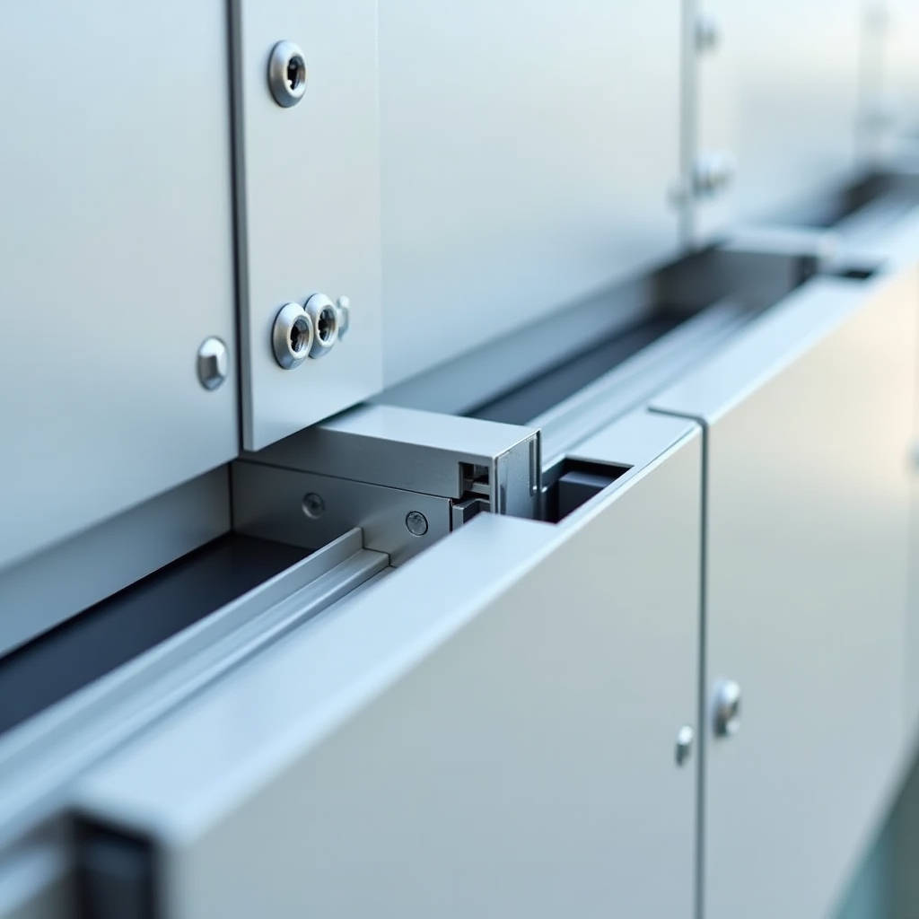
When a facade panel detaches at 40 meters above street level, the failure rarely traces back to the aluminium sheet itself. More often, the investigation leads to a small component that cost less than 2% of the total cladding budget: the Aluminum Fixing Clip. These connectors sit between the solid aluminium panel and the building's substructure, absorbing wind loads, thermal movement, and dead weight simultaneously. A poorly specified clip can compromise an entire rainscreen system regardless of how well the 3.0mm PVDF-coated panels were fabricated. This article examines the structural logic, material selection, and failure mechanisms that engineers and procurement managers need to understand before signing off on clip specifications for solid aluminium cladding projects.
What an Aluminum Fixing Clip Actually Does in a Rainscreen
In solid aluminium cladding systems, the fixing clip is not merely a bracket. It functions as a structural intermediary that transfers three distinct load types from the panel to the building frame. Wind suction (negative pressure) tries to pull the panel outward. Wind pressure pushes it inward. Thermal expansion and contraction — which can reach 2.4mm per linear meter for aluminium across a 100°C temperature swing — creates cyclical shear forces at every connection point. The clip must accommodate this movement without loosening, cracking, or transferring stress into the panel itself.
The standard configuration for a 2.5mm or 3.0mm solid aluminium panel uses a clip-and-rail system. The clip body, typically extruded from 6063-T6 aluminium alloy, engages with a continuous aluminium rail that has been pre-attached to the rear of the panel using structural-grade adhesive or mechanical fasteners. The clip then bolts or screws to the vertical or horizontal substructure — usually galvanized steel or aluminium help rails. The critical engineering detail is the clip's geometry at the engagement point: a 3-5mm gap between the clip face and the panel rail allows for thermal movement while maintaining positive engagement under wind suction.
What separates a properly engineered clip from a generic bracket is the incorporation of a defined engagement depth and pull-out resistance value. Reputable manufacturers test clip assemblies to failure under ASTM E330 (uniform static air pressure difference) and provide the resulting allowable load data. Without this, the specifier is guessing.
Material Selection: Why 6063-T6 Dominates
The choice of aluminium alloy for fixing clips is not arbitrary. 6063-T6 offers a balance of extrudability (allowing complex cross-sections with tight tolerances), corrosion resistance, and mechanical strength. Its tensile strength of approximately 240 MPa and yield strength around 215 MPa provide sufficient capacity for typical cladding loads while maintaining enough ductility to avoid brittle fracture under cyclic loading.
Some manufacturers offer clips in 6061-T6, which provides higher tensile strength (approximately 310 MPa) but is more difficult to extrude into the fine profiles required for clip engagement. For most commercial and residential cladding applications, 6063-T6 is the correct specification. For high-rise projects in extreme wind zones — where calculated suction pressures exceed 3.0 kPa — 6061-T6 clips may be warranted, but the cost increase (typically 15-25%) must be weighed against the actual load requirements.
Corrosion protection deserves equal attention. Bare extruded aluminium forms a natural oxide layer, but in marine or industrial environments, this passive protection is insufficient. Clips should be anodized to a minimum of AA-M10C22A31 (Class I architectural anodizing, 17-20 microns) or receive a two-coat PVDF finish matching the panel specification. The latter is particularly important when clips are visible in open-joint systems. A common failure mode observed in coastal projects is pitting corrosion at the clip-to-fastener interface, where dissimilar metal contact between the aluminium clip and a stainless steel screw creates galvanic corrosion if not properly isolated with a nylon washer or EPDM gasket.
Load Path Analysis: Where Clips Fail
Understanding the load path reveals why clip failures concentrate at specific points. When wind suction acts on a 1,200mm x 3,000mm solid aluminium panel, the force is distributed across all clips supporting that panel. A typical layout uses four clips per panel — two at the top rail, two at the bottom. If the panel spans 3 meters vertically, each clip carries approximately 25% of the total wind load plus its share of the dead load (a 3.0mm aluminium panel of that size weighs approximately 29 kg).
The failure chain usually begins at the fastener connection rather than the clip body itself. A self-tapping screw into a 2mm-thick galvanized steel help rail might have a pull-out capacity of only 1.2 kN in tension. Compare this to a properly specified M6 machine screw into a 4mm aluminium rail, which can achieve 4.5 kN or more. The clip body might be rated for 6 kN, but the assembly is only as strong as its weakest link.
Another failure mechanism involves creep in the structural adhesive that bonds the panel rail to the rear of the solid aluminium sheet. Two-part structural tapes and liquid adhesives used in cassette systems must maintain bond strength across the full service temperature range (-20°C to +80°C). A study published by the Centre Scientifique et Technique du Bâtiment (CSTB) demonstrated that some adhesive systems lose up to 40% of their initial bond strength after 20 years of thermal cycling. When the adhesive creeps, the rail shifts, the clip engagement changes, and the load distribution across the panel becomes unpredictable.
Thermal Movement: The Engineering Detail Most Specifications Miss
Aluminium expands at approximately 0.024mm per meter per degree Celsius. For a 4-meter-long panel subjected to a 60°C temperature rise from installation temperature (winter morning to summer afternoon on a dark-colored facade), the total expansion is 5.76mm. If the fixing clips restrain this movement rigidly, the panel will buckle. If the clips allow too much movement, the panel can rattle under wind gusting.
The solution lies in the clip design. Fixed-point clips (also called "anchor clips") are installed at one location on each panel — typically the center of the top edge — and provide positive location in all directions. All other clips are "sliding clips" that restrain the panel in the out-of-plane direction (wind load) but allow vertical and horizontal movement through an elongated slot or a sliding engagement detail. The sliding clip's slot length must equal or exceed the calculated thermal movement for that panel dimension plus a safety factor of 1.5.
The table below summarizes the required slot lengths for common panel sizes based on a 100°C maximum temperature differential:
| Panel Dimension (mm) | Max Thermal Movement (mm) | Minimum Slot Length (mm) | Recommended Clip Type |
|---|---|---|---|
| 600 x 1200 | 1.44 | 2.2 | Standard sliding, 6063-T6 |
| 1200 x 2400 | 2.88 | 4.4 | Heavy sliding, 6063-T6 |
| 1500 x 3000 | 3.60 | 5.4 | Heavy sliding, 6063-T6 |
| 1200 x 4000 | 4.80 | 7.2 | Heavy sliding, 6061-T6 |
| 1500 x 5000 | 6.00 | 9.0 | Custom engineered, 6061-T6 |
Failing to distinguish between fixed and sliding clips in the shop drawing review is one of the most common errors on cladding projects. The consequences — oil-canning, fastener fatigue, and in severe cases, panel detachment — are entirely avoidable through proper specification.
Clip Spacing and Quantity: Calculating What You Actually Need
The number of clips per panel is not a matter of preference; it is a structural calculation. The governing equation is straightforward:
Required clips per panel = (Design wind pressure × Panel area) / (Allowable clip load × Safety factor)
For a project in a region with a design wind pressure of 2.0 kPa (typical for many mid-rise urban locations), a 1,200mm x 3,000mm panel (3.6 m²) experiences a total wind force of 7.2 kN. If the specified Aluminum Fixing Clip has an allowable tensile load of 2.0 kN (after applying a safety factor of 2.5 to the ultimate tested capacity of 5.0 kN), the calculation yields 3.6 clips. Rounding up, four clips are required.
However, this calculation assumes uniform load distribution. In reality, corner panels on a building experience significantly higher suction pressures — up to 2.5 times the field pressure according to ASCE 7 wind load provisions. Corner panels may require six clips rather than four, and the clips themselves may need to be upgraded to a higher capacity model. The cost difference between four standard clips and six heavy-duty clips per corner panel is modest — perhaps $12-18 per panel — but the consequence of under-specification is a potential facade failure.
For procurement managers, this has direct implications. A mid-rise office building with 2,000 m² of solid aluminium cladding might use approximately 550 panels. If 15% of those are corner panels requiring additional clips, the total clip count increases by roughly 165 units. At a unit cost of $3-8 per clip (depending on specification), this represents a $500-1,300 line item — negligible against the total facade budget but critical to structural integrity.
Corrosion Compatibility: The Galvanic Series in Practice
Every fixing clip exists within an electrochemical environment. The clip is aluminium. The fastener is typically stainless steel (A2 or A4 grade). The substructure might be galvanized steel, aluminium, or even timber in some residential applications. Where dissimilar metals meet in the presence of an electrolyte (rainwater, condensation), a galvanic cell forms, and the less noble metal corrodes preferentially.
Aluminium sits below stainless steel on the galvanic series. In a clip-to-fastener connection, the aluminium clip is the anode and will corrode if the interface is not properly isolated. The solution is straightforward: use a nylon or EPDM isolating washer between the clip and the stainless steel screw head, and apply a thread-locking compound that also serves as a barrier to moisture ingress. For marine environments (within 5 km of a coastline), specify A4 (316) stainless steel fasteners rather than A2 (304), and ensure the clip anodizing thickness meets the Class I architectural standard.
The American Architectural Manufacturers Association (AAMA) publishes guidelines on dissimilar metal contact in their AAMA 2605 and related documents. While these standards primarily address coating performance, the underlying principles of corrosion protection apply directly to clip and fastener specification.
Installation Tolerances and Quality Control
Even the best-engineered clip performs poorly if installed incorrectly. The critical installation parameters include:
- Clip alignment: All clips on a given horizontal rail must be co-planar within ±1.0mm. A misaligned clip forces the panel rail into a twisted engagement, concentrating stress at the clip edges rather than distributing it across the full bearing surface.
- Fastener torque: Over-torquing a self-tapping screw into an aluminium help rail strips the thread and reduces pull-out capacity by 30-50%. Under-torquing leaves the connection loose. The correct torque value for an M6 stainless steel screw into 6063-T6 aluminium is typically 8-10 Nm, but this should be confirmed with the clip manufacturer.
- Edge distance: Clips must be positioned at least 50mm from the panel edge to avoid edge-tear-out failure modes. For panels with folded returns, the clip position must account for the return leg geometry.
On large projects, a mock-up installation is essential. A 3m x 3m section of the facade, installed with the actual specified clips, rails, fasteners, and panels, should be subjected to a water spray test (ASTM E1105) and, ideally, a static pressure test. This reveals integration issues — clip-to-rail misalignment, inadequate slot length for thermal movement, fastener interference — before they propagate across thousands of square meters of facade.
Supply Chain Considerations for International Projects
For procurement managers sourcing cladding systems across borders, the Aluminum Fixing Clip represents a disproportionate source of risk. The panels themselves are straightforward to specify: 2.5mm or 3.0mm solid aluminium, 5754 or 3003 alloy, PVDF coating to AAMA 2605. The clips, however, are often treated as a commodity item and sourced from the lowest bidder.
This is a mistake. A clip that meets the dimensional specification but is extruded from a lower-grade alloy (or from recycled material with uncontrolled composition) may fail in service. The failure might not manifest for 3-5 years, by which time the original supplier may be unreachable. Key supply chain controls include:
- Mill certification: Require certificates showing the aluminium alloy composition and temper for each batch of extrusions.
- Pull-out testing: Conduct sample testing of the clip-to-rail engagement at an accredited laboratory. The test should apply tensile load at a rate of 2mm/min until failure, with the failure mode documented (clip fracture, rail disengagement, or fastener pull-out).
- Batch traceability: Each clip should be marked with a batch code that traces back to the extrusion lot and anodizing batch.
Suppliers with vertically integrated production — where extrusion, machining, and surface treatment occur under one quality management system — reduce the risk of batch-to-batch variability. Futeng®, for example, maintains in-house extrusion capabilities for aluminium cladding accessories including fixing clips, which allows for direct control over alloy composition and dimensional tolerances. This level of integration is worth considering when specifying for projects where facade performance is non-negotiable.
Cost Breakdown: Clips in the Total Facade Budget
Understanding the cost structure helps procurement teams make informed decisions. The table below provides indicative cost ranges for a typical mid-rise commercial project using solid aluminium cladding panels:
| Component | Cost per m² (USD) | Percentage of Total | Notes |
|---|---|---|---|
| 3.0mm solid aluminium panel, PVDF coated | $85-120 | 55-65% | Includes fabrication, folding, routing |
| Aluminium substructure (help rails, brackets) | $25-40 | 15-20% | Vertical and horizontal rails |
| Aluminum Fixing Clips (standard, 6063-T6) | $3-6 | 2-4% | 4 clips per panel average |
| Fasteners (screws, bolts, washers) | $2-4 | 1-2% | Stainless steel, A2 or A4 |
| Thermal insulation | $8-15 | 5-8% | Mineral wool, 80-120mm |
| Installation labor | $30-50 | 20-25% | Varies by region and complexity |
The clip line item represents 2-4% of the total facade cost. Upgrading from a standard clip to a heavy-duty model with enhanced corrosion protection might add $1-2 per m² — a 1% increase in total cost that buys a significant margin of safety. Conversely, saving $1 per m² by specifying an unverified clip product introduces a risk that is entirely disproportionate to the cost saving.
Specifying Clips for High-Wind and Seismic Zones
Projects in hurricane-prone regions (Florida, the Caribbean, Southeast Asia, northern Australia) and seismic zones (California, Japan, New Zealand) impose additional demands on fixing clip design. In high-wind zones, the governing load case is often wind suction during a storm event, with design pressures reaching 4.0-6.0 kPa. This requires clips with higher pull-out capacity, closer spacing, and positive mechanical engagement rather than friction-based connections.
In seismic zones, the challenge is different. The building frame deflects laterally during an earthquake, and the cladding system must accommodate inter-story drift without shedding panels. The clip-to-rail connection must allow for in-plane movement of ±15-25mm (depending on the calculated drift) while maintaining out-of-plane restraint. This is typically achieved through slotted connections with a defined slip range, combined with a secondary retention mechanism that prevents the panel from disengaging even if the primary clip reaches its movement limit.
The FEMA guidelines for seismic design of nonstructural components (FEMA E-74) provide a framework for specifying cladding connections in seismic zones. The key principle is that the connection must be ductile — it should yield and deform rather than fracture. For aluminium clips, this means specifying an alloy and temper with sufficient elongation at break (minimum 8% for 6063-T6, ideally 10-12% for seismic applications).
Common Specification Errors and How to Avoid Them
Drawing on project experience across multiple continents, several specification errors recur with enough frequency to warrant explicit attention:
- Specifying clip material as "aluminium" without alloy designation: This invites substitution of unknown or recycled alloys. Always specify "6063-T6 extruded aluminium" or "6061-T6 extruded aluminium" as applicable.
- Omitting the sliding clip requirement: A specification that calls for identical clips at all locations ignores thermal movement. The shop drawings must clearly distinguish fixed and sliding clip positions.
- Ignoring the clip-to-fastener interface: The clip is only as strong as the screw that holds it. Specify the fastener type, diameter, material grade, and torque value.
- Failing to account for panel weight in overhead installations: Soffit panels and canopy installations place clips in sustained tension. Creep in the clip material and the fastener connection must be considered over the design life of the building.
- No corrosion protection specification: "Aluminium clip" without a finish specification will result in mill-finish extrusions that may corrode within months in aggressive environments.
The ISO 9227 salt spray test standard provides a useful reference for specifying corrosion resistance requirements. A clip that withstands 1,000 hours of neutral salt spray testing without significant pitting is suitable for most urban and light industrial environments. For marine environments, 2,000 hours is a more appropriate benchmark.
Practical Recommendations for Project Teams
Based on the engineering analysis presented, the following recommendations apply to most solid aluminium cladding projects:
First, treat the Aluminum Fixing Clip as a structural component, not a commodity accessory. The specification should be as detailed as the panel specification, covering alloy, temper, finish, dimensional tolerances, and allowable load values. Second, require pull-out test data from the clip manufacturer for the specific clip-to-rail combination proposed for the project. Generic load tables that do not reference a specific rail profile are insufficient. Third, invest in a physical mock-up that includes at least four full panels with all clips, rails, and fasteners installed as they will be on the building. Test the mock-up under water spray and, if possible, static pressure. Fourth, for projects in demanding environments — marine, industrial, high-wind, seismic — engage a facade engineer to review the clip specification and shop drawings before fabrication begins.
The engineering reality is straightforward: a facade is a system, and the performance of the system is determined by its weakest component. When that component is a $4 clip, the cost of getting it right is trivial compared to the cost of getting it wrong.