Aluminum Clip Engineering for Solid Aluminium Cladding Load Paths and Corrosion Control
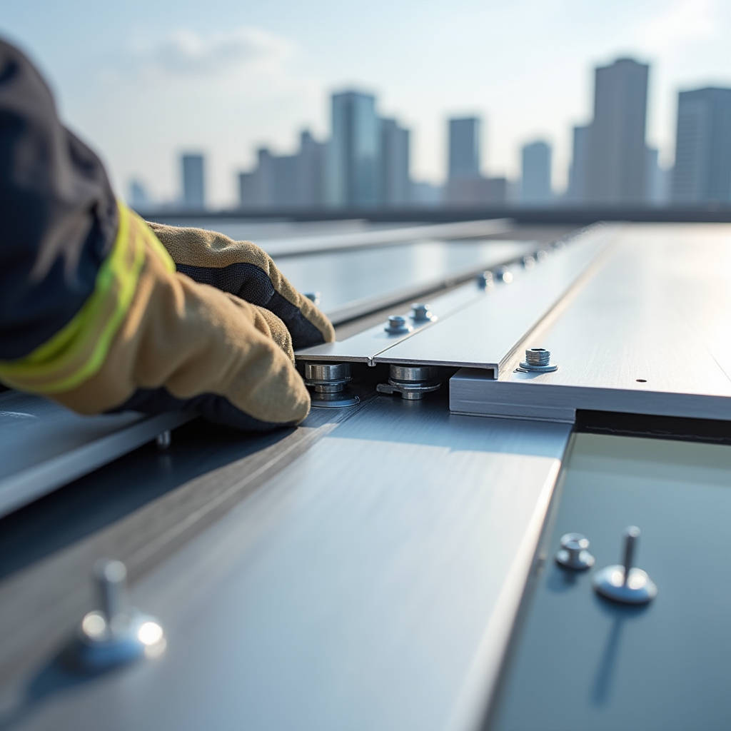
When a cladding panel fails on a high-rise, the root cause rarely traces back to the visible aluminium face. More often, the failure begins at a connection point no larger than a thumb — the clip. An Aluminum Clip in solid aluminium cladding systems serves as the mechanical bridge between the building substrate and the panel itself. It absorbs wind suction, accommodates thermal movement, and transfers dead loads back to the structural frame. Getting the clip specification right means the difference between a facade that performs for 40 years and one that requires remedial work within five. This article examines the engineering logic behind clip selection for solid aluminium panels, with a focus on alloy compatibility, corrosion risk, load distribution, and the practical realities of installation tolerances on commercial projects.
Why the Clip Matters More Than the Panel
Solid aluminium cladding panels — typically 2.0mm, 2.5mm, or 3.0mm thick sheets formed from 3003 or 5052 alloy — carry inherent structural integrity. A 3.0mm thick panel spanning 1,200mm between supports resists deflection through its own section modulus. But the panel is only as stable as its anchorage. The Aluminum Clip transfers every newton of wind load, every cycle of thermal expansion, and every kilogram of dead weight from the panel to the substructure. On a 100-meter tower with 8,000 square meters of cladding, the collective clip system might handle over 200,000 individual load transfer points. Specifying a clip without understanding the load path is like designing a bridge without calculating bearing capacity.
The clip's function extends beyond simple retention. It must allow the panel to move independently of the substrate. Solid aluminium expands at roughly 2.4 mm per linear meter across a 100°C temperature delta. A rigid connection that ignores this movement will cause panel buckling, fastener fatigue, or sealant shear. The clip geometry — whether a Z-profile, a hat section, or a custom extrusion — determines how much slip capacity exists in the system.
Aluminium Clip vs. Stainless Steel Clip: The Galvanic Corrosion Reality
One of the most common specification errors on cladding projects involves mixing clip and fastener materials without accounting for galvanic potential. An Aluminum Clip paired with an aluminium panel creates a matched system with minimal electrochemical difference. The corrosion risk stays low even in marine or industrial environments. But when a stainless steel clip contacts an aluminium panel in the presence of an electrolyte — rain, condensation, or coastal salt spray — the aluminium becomes the anode and sacrifices itself.
The galvanic series tells the story. In seawater, 3003 aluminium sits at approximately -0.79V, while 304 stainless steel sits at around -0.35V. That 0.44V differential drives corrosion. The aluminium panel, with its large surface area relative to the small stainless clip contact point, experiences accelerated pitting at the interface. The solution is not always to avoid stainless steel — sometimes project specifications demand it for fire rating or strength — but to isolate the two metals with a non-conductive barrier: nylon washers, EPDM gaskets, or a factory-applied isolation coating on the clip face.
| Clip Material | Galvanic Potential (V vs SCE) | Compatible Panel Alloy | Corrosion Risk (C3 Environment) | Recommended Isolation | Typical Cost Index |
|---|---|---|---|---|---|
| 6063-T5 Aluminium | -0.83 | 3003 / 5052 | Negligible | None required | 1.0 |
| 304 Stainless Steel | -0.35 | 3003 / 5052 | Moderate to High | EPDM gasket + nylon washer | 1.4 |
| 316 Stainless Steel | -0.30 | 5052 (Marine Grade) | Moderate | EPDM gasket + nylon washer | 1.7 |
| Hot-Dip Galvanized Steel | -1.05 | 3003 / 5052 | Severe (Zinc Sacrifice) | Full isolation mandatory | 0.7 |
The table above reflects real-world data aligned with ASTM G82 and ISO 9223 classifications. For C4 and C5-M environments — coastal industrial zones, offshore platforms — the recommendation shifts decisively toward 6063-T5 aluminium clips with PVDF or anodized finishes, eliminating the galvanic couple entirely.
Clip Geometry: Z-Clips, Hat Clips, and Custom Extrusions
The Aluminum Clip market offers several standard profiles, but the distinction between them is not cosmetic. Each geometry solves a different set of installation and performance problems.
Z-Clips: The Workhorse of Interior and Light Exterior Applications
Z-clips consist of two interlocking aluminium extrusions — one mounted to the wall, one attached to the panel back. The angled interlock draws the panel tight against the substrate as gravity seats the two halves together. For interior feature walls, acoustic panels, and soffit linings, Z-clips provide a clean, fastener-free face. The standard 1-inch width with 0.240-inch projection handles panel weights up to approximately 15 kg per clip pair. On a 1,200mm x 600mm panel weighing 4.9 kg (2.5mm thick 3003 alloy), two Z-clip pairs provide a safety factor exceeding 6:1.
But Z-clips have limitations. They rely on gravity for engagement. On overhead soffits or in high-vibration environments — near rail lines, industrial machinery — the interlock can loosen over time unless supplemented with a mechanical lock or set screw. Wind uplift on exterior facades can momentarily unload the clip, creating a rattling condition that fatigues the aluminium over thousands of cycles.
Hat Clips and Routed Systems
For exterior solid aluminium cladding, the industry standard leans toward hat-shaped clips that engage a routed groove in the panel edge. The clip body, typically extruded from 6063-T6 aluminium, provides a continuous bearing surface along the panel perimeter. Fasteners pass through the clip into the substructure — aluminium mullions, steel girts, or adjustable brackets — while the panel edge floats within the clip pocket. This detail accommodates thermal movement in both directions while maintaining positive mechanical engagement.
The critical dimension in a hat clip system is the groove depth and the clip leg length. A 3.0mm panel with a 10mm-deep routed groove engaging a clip leg of 9.5mm leaves 0.5mm of clearance for movement. Too tight, and the panel binds. Too loose, and wind-induced vibration causes noise and accelerated wear. The engineering tolerance stack must account for panel fabrication accuracy (±0.5mm), clip extrusion tolerance (±0.3mm), and site installation variation (±1.0mm).
Custom Extrusions for High-Performance Facades
On projects with complex geometry — curved panels, large-format units exceeding 4 meters in length, or facades requiring specific fire performance — off-the-shelf clips rarely suffice. Custom Aluminum Clip extrusions allow the engineer to optimize the cross-section for the specific load case. A clip designed for a 50-story tower in a typhoon zone might incorporate a thicker web, a longer bearing leg, and an integrated EPDM pressure pad. The die cost for a custom extrusion — typically $2,000 to $5,000 — amortizes quickly across 10,000 linear meters of cladding.
Futeng® has supplied custom clip profiles for projects where standard geometries could not meet the combined demands of wind load, seismic drift, and thermal cycling. The engineering process involves finite element analysis of the clip cross-section under the project's specific design loads, followed by extrusion trials and mechanical testing to verify ultimate capacity and fatigue life.
Load Calculation: What Your Clip Actually Needs to Handle
Specifying an Aluminum Clip without running the numbers is gambling. The three load cases every clip must survive are wind load, dead load, and thermal load — and they often act simultaneously.
Wind Load: For a building in Exposure Category B with a basic wind speed of 45 m/s (ASCE 7-22), the design wind pressure on a corner zone can reach 2.4 kPa (negative, suction). On a 1.5m x 1.0m panel, that translates to 3,600 N of suction force distributed across the perimeter clips. With four clips per panel, each clip sees 900 N. The clip's pull-out capacity — determined by the fastener type, substrate material, and clip geometry — must exceed this with a safety factor of at least 2.0 per AAMA 501.4.
Dead Load: A 3.0mm thick solid aluminium panel at 1,500mm x 1,000mm weighs approximately 12.2 kg (119.6 N). On a vertical facade, the clips carry this as shear. The bearing area of the clip leg against the panel groove distributes the load. At 119.6 N across a bearing area of 150 mm², the bearing stress is 0.8 MPa — well within the allowable bearing stress of 6063-T6 aluminium (approximately 145 MPa yield). The numbers work, but only if the clip is properly seated and the groove is clean.
Thermal Load: A 3-meter-long panel experiencing a 60°C temperature swing expands by 4.3 mm. If the clip system restrains this movement, the induced stress can reach 30 MPa — enough to buckle a thin panel or shear a fastener. The clip must allow slip. A properly designed hat clip with a slotted fastener hole in the substructure connection provides 6-8 mm of travel, accommodating the thermal movement without inducing stress.
Material Selection: Alloy, Temper, and Finish
The aluminium alloy choice for clips is not arbitrary. Extruded clips typically use 6063-T5 or 6063-T6, offering good extrudability, reasonable strength (145-215 MPa ultimate tensile), and excellent corrosion resistance. For higher-strength requirements, 6061-T6 extrusions push the ultimate tensile strength to 310 MPa, but at the cost of slightly reduced corrosion resistance and higher die wear.
The finish on the clip matters as much as the panel finish. An uncoated 6063 clip in a C3 environment will develop a thin oxide layer and remain stable. But in C4 or C5 environments, the clip needs protection. Anodizing to AA-M10C22A31 (Class I, 20 microns) provides excellent durability. Alternatively, a PVDF coating matching the panel specification — 70% PVDF resin, minimum 30 microns dry film thickness per AAMA 2605 — ensures the clip and panel age at the same rate with the same appearance.
For projects where the clip remains visible — open-joint rain screen systems, for example — the finish must match the panel exactly. Colour variation between the clip and panel becomes visible in the shadow gap. This is where a single-source supplier providing both panels and matching clips eliminates the risk of metameric failure under different light sources.
Installation Tolerances: Where Theory Meets the Site
The best-engineered Aluminum Clip system fails if the substructure is 15 mm out of plane. Solid aluminium cladding demands a substrate tolerance of ±3 mm over 3 meters, measured with a straight edge per AAMA 501.9. The clip system must provide enough adjustment range — typically ±10 mm in the Z-axis through slotted brackets — to absorb substrate irregularities while maintaining the panel plane within ±2 mm.
Three-dimensional adjustability separates professional clip systems from basic hangers. A clip that adjusts only in the Z-direction forces the installer to shim or pack the substructure, adding labour cost and introducing variable bearing conditions. A clip system with independent X, Y, and Z adjustment — through a combination of slotted holes, serrated washers, and threaded studs — allows the installer to dial in the panel position precisely. The time saved per panel multiplies across thousands of units on a commercial facade.
On a recent mid-rise project, the switch from a fixed Z-clip to a 3D-adjustable hat clip system reduced panel installation time from 12 minutes to 7 minutes per unit. Across 2,400 panels, that saved 200 labour hours. The higher unit cost of the adjustable clip was recovered within the first 500 panels through labour savings alone.
Fire Performance Considerations
Solid aluminium cladding — unlike ACP with its polyethylene core — is inherently non-combustible. The aluminium panel itself carries a Euroclass A1 rating (EN 13501-1) or passes ASTM E136 as non-combustible. But the clip system must not compromise this performance. Nylon washers used for galvanic isolation, EPDM gaskets, and plastic shims all introduce combustible elements into the assembly.
The Aluminum Clip system for fire-rated facades should minimize or eliminate polymeric components. Where isolation is required, thin PTFE or ceramic fibre gaskets provide the necessary dielectric barrier without adding fuel load. The clip material itself — solid aluminium — remains stable up to its melting point of approximately 660°C, well above the temperatures typically reached in a facade cavity fire before sprinkler activation or fire service intervention.
Testing per NFPA 285 or BS 8414 evaluates the complete wall assembly, including clips, insulation, and cavity barriers. Specifying clips that have been included in successfully tested assemblies provides a defensible engineering position. Some manufacturers maintain a library of tested assemblies that specifiers can reference rather than commissioning project-specific testing.
Cost Breakdown: Clip System Economics
The Aluminum Clip represents a small fraction of the total cladding system cost — typically 3% to 8% — but its influence on long-term performance is disproportionate. The table below breaks down the cost components for a typical 1,000 m² solid aluminium cladding project.
| Cost Component | Standard Z-Clip System | 3D-Adjustable Hat Clip System | Custom Extruded Clip System |
|---|---|---|---|
| Clip Material Cost (per m²) | $8.50 | $14.20 | $19.80 |
| Fasteners & Accessories (per m²) | $3.20 | $4.60 | $5.10 |
| Installation Labour (per m²) | $22.00 | $16.50 | $15.00 |
| Adjustment & Realignment (per m²) | $4.50 | $1.20 | $0.80 |
| Total Installed Cost (per m²) | $38.20 | $36.50 | $40.70 |
| 10-Year Maintenance Liability | Moderate | Low | Very Low |
The numbers reveal a counterintuitive truth: the cheapest clip system is not the cheapest installed system. The 3D-adjustable hat clip, despite higher material cost, delivers the lowest total installed cost due to labour efficiency. The custom extrusion, while slightly more expensive overall, eliminates the maintenance liability that erodes the apparent savings of the basic Z-clip approach.
Specifying Clips for Seismic Zones
In regions governed by ASCE 7 seismic design requirements — the western United States, Japan, New Zealand, Turkey — the clip system must accommodate inter-story drift without losing panel retention. A typical design drift of H/50 (where H is the floor-to-floor height) at 3.6 meters produces 72 mm of lateral displacement between floors. The clip must allow the panel to move with the drift while remaining engaged.
This requires a clip with a longer engagement leg and a wider pocket, allowing the panel edge to slide laterally without disengaging. Some systems incorporate a secondary retention tab — a mechanical stop that prevents the panel from walking out of the clip under cyclic loading. The AAMA 501.4 test protocol evaluates this performance through cyclic displacement testing, and specifying clips that have passed this test provides documented assurance of seismic performance.
Quality Control: What to Check Before Installation
Before any Aluminum Clip reaches the site, the specification should mandate mill certificates for the extrusion alloy and temper, dimensional inspection reports for the cross-section, and finish thickness measurements. On arrival, a random sample — typically 5% of the shipment per ASTM E122 — should undergo dimensional verification with calipers and a go/no-go gauge matching the panel groove geometry.
The most common defect found in clip shipments is inconsistent extrusion die wear. As the die wears, the clip leg thickness increases, and the interlock geometry drifts. A clip that measures 0.5 mm oversize on the leg may not engage the panel groove at all, or may require excessive force that damages the panel edge. Catching this at the factory rather than on the scaffold saves weeks of delay and thousands in rework.
For projects where the clip finish must match the panel, colour and gloss should be verified under both D65 daylight and F2 fluorescent light sources to catch metamerism. A spectrophotometer reading with a Delta E of less than 1.0 between clip and panel under both light sources is the industry benchmark for an acceptable match.
Summary: Engineering the Connection
The Aluminum Clip is not a commodity item to be selected from a catalogue based on price alone. It is an engineered component that determines the structural performance, corrosion resistance, thermal behaviour, and installation efficiency of the entire solid aluminium cladding system. The specification process should follow a logical sequence: calculate the design loads, select the clip material and geometry to match, verify galvanic compatibility, confirm adjustment range for site tolerances, and validate through testing or documented precedent. Projects that treat the clip as an afterthought invariably pay for it later — in callbacks, in remedial work, and in the slow erosion of the facade's reputation. The clip is small. The consequences of getting it wrong are not.