Aluminum Cleat Engineering for Solid Aluminium Facade Systems Load Paths and Material Specifications
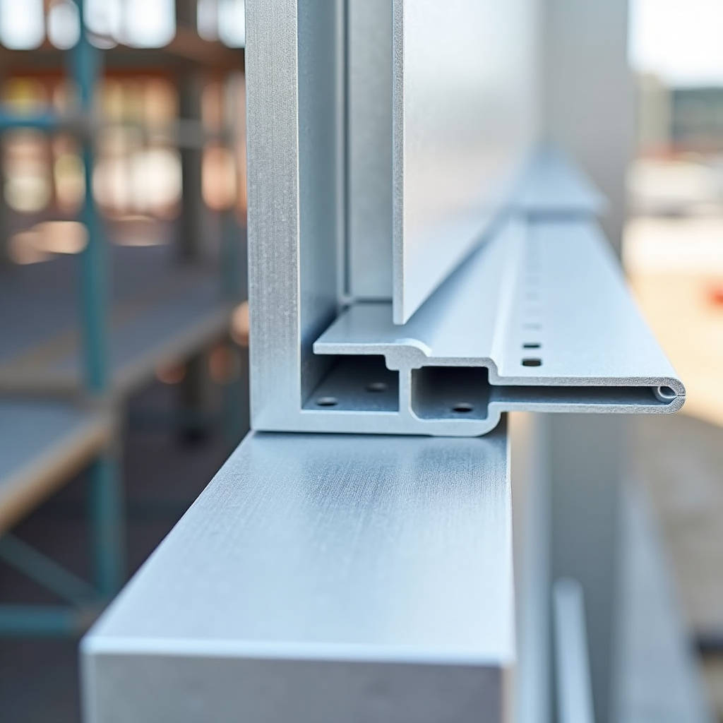
When a facade panel pulls away from a high-rise in 90 mph wind, the failure rarely starts with the panel itself. It starts at the connection. The Aluminum Cleat — a small, precisely engineered bracket hidden behind the cladding — carries the full weight of the panel and every pound of wind load transferred through the system. On a 30-story tower, a single cleat might bear 200 to 400 pounds of combined dead and live load, repeated across thousands of attachment points. Getting the alloy, geometry, and fastener specification right is not a detail. It is the difference between a facade that holds for 50 years and one that becomes a liability in its first major storm.
What an Aluminum Cleat Actually Does in a Rainscreen System
In solid aluminium cladding assemblies, the cleat is the intermediary component that connects the panel to the vertical rail or subframe. Unlike marine deck cleats that serve as tie-down points for ropes, a facade cleat is a structural bracket — typically L-shaped, Z-shaped, or custom-fabricated — that transfers loads from the panel face into the building's primary structure.
The cleat performs three distinct engineering functions. First, it provides dead load support, carrying the self-weight of the aluminium panel (roughly 5.4 kg/m² for 2.0mm sheet, scaling to 8.1 kg/m² for 3.0mm). Second, it resists wind suction and pressure, which on a coastal high-rise can exceed 3.0 kPa. Third, it accommodates thermal movement. Solid aluminium expands at approximately 0.024 mm per meter per degree Celsius. A 4-meter panel cycling through a 50°C temperature swing moves nearly 5 mm. The cleat must allow this movement without binding, buckling, or transferring stress into the panel face.
This is why the Aluminum Cleat in facade engineering bears almost no resemblance to the cast cleats found on docks and boats. Facade cleats are extruded or press-braked from specific alloy grades, machined with slotted holes, and sometimes paired with nylon bushings or isolation pads to prevent galvanic corrosion where they contact steel substructures.
Alloy Selection: Why 6061-T6 and 5052 Dominate Facade Cleat Production
Not every aluminium alloy belongs on a building envelope. The cleat sits in a high-stress, exposed position where strength, corrosion resistance, and formability all matter. Two alloys have emerged as the standard for facade cleat fabrication.
6061-T6 offers a tensile strength of roughly 310 MPa and yield strength around 276 MPa. It extrudes cleanly, machines well, and holds tight dimensional tolerances — critical when cleats must align with pre-drilled panel holes across hundreds of units. Its magnesium-silicon composition provides good atmospheric corrosion resistance, though in marine or industrial environments, an anodized or PVDF-coated finish is standard practice.
5052-H32, with tensile strength near 228 MPa, sacrifices some stiffness for superior formability and saltwater resistance. Its higher magnesium content (2.2–2.8%) makes it the preferred choice for press-braked cleats in coastal projects. The alloy resists pitting and intergranular corrosion even in chloride-heavy air, which matters when the cleat sits inside a ventilated cavity exposed to whatever the wind drives through the open joints.
Some fabricators use 3003-H14 for light-duty interior applications, but its lower yield strength (roughly 145 MPa) limits its use to non-structural trim. For any cleat carrying panel weight on an exterior facade, 6061-T6 or 5052-H32 should be the minimum specification. Projects requiring third-party testing — which is increasingly common in markets like Australia, the Middle East, and Southeast Asia — will almost always specify one of these two grades.
Geometry Matters: Cleat Profiles and Their Load Paths
The shape of an Aluminum Cleat determines how efficiently it transfers load. Three profiles dominate the market, each with distinct structural behavior.
L-Shaped Cleats
The simplest and most common configuration. One leg bolts to the vertical rail; the other leg supports the panel bottom edge. The bend radius is critical — too tight and the material work-hardens and cracks under cyclic loading. A minimum inside bend radius of 1.5 times material thickness is standard for 6061-T6. For a 3.0mm thick cleat, that means a 4.5mm minimum radius. L-cleats work well for flat panels under moderate wind loads but provide limited resistance to torsional forces.
Z-Shaped Cleats
The Z-profile creates an offset between the rail attachment plane and the panel support plane. This geometry allows the panel to sit flush with the insulation layer while the rail stands off the substrate. The two bends in a Z-cleat introduce additional stress concentration points, so material thickness often increases by 0.5–1.0mm compared to an equivalent L-cleat. The advantage is installation flexibility — Z-cleats can accommodate thicker insulation without requiring deeper subframe sections.
Custom Cassette Cleats
For unitized or cassette panel systems, cleats are often bespoke extrusions with integrated hooks, anti-rattle springs, and slotted adjustment channels. These are die-cast or machined from 6061-T6 billets and represent the high end of cleat engineering. A single custom cleat might combine dead load support, wind load restraint, and lateral adjustment in one component. The tooling cost is higher, but on projects exceeding 5,000 m², the labor savings from faster installation typically offset the upfront investment.
Wind Load Calculations: Sizing Cleats by the Numbers
Cleat spacing is not a guess. It follows directly from the project's wind load analysis and the panel dimensions. The calculation path is straightforward but unforgiving of shortcuts.
Start with the design wind pressure (P) from the local building code — ASCE 7 in the United States, EN 1991-1-4 in Europe, AS/NZS 1170.2 in Australia and New Zealand. For a mid-rise building in a suburban exposure, P might be 1.5 kPa. On a 40-story coastal tower, it could reach 3.5 kPa or higher at corner zones.
Multiply P by the panel's tributary area per cleat. If panels are 1.2 meters wide and cleats are spaced every 0.6 meters vertically, each cleat serves 0.72 m². At 3.5 kPa, that means 2.52 kN (roughly 257 kg-force) of wind load per cleat — plus the panel's self-weight of about 40–60 N per cleat depending on thickness.
The cleat's cross-sectional area at its critical section must resist this combined load without exceeding the material's allowable stress. For 6061-T6, a safety factor of 1.65 on yield is common, giving an allowable stress around 167 MPa. A cleat with a 20 mm × 3 mm cross-section (60 mm²) at the critical bend can theoretically handle about 10 kN in pure tension — but bending and buckling reduce this significantly. Finite element analysis or physical load testing is standard practice for any project where wind loads exceed 2.0 kPa.
The cleat is the cheapest component in the facade assembly and the most expensive one to get wrong. A $3 bracket failing in shear can trigger a six-figure remediation.
Corrosion and Galvanic Compatibility: The Hidden Specification
Aluminium cleats bolted to galvanized steel rails create a galvanic cell. In the presence of moisture — and rainscreen cavities are rarely dry — the aluminium, being more anodic, will corrode preferentially. The severity depends on the environment. Inland, the corrosion rate might be negligible. Within 5 kilometers of breaking surf, it can be aggressive enough to compromise a cleat within 10 years.
The standard defense is isolation. Nylon or EPDM washers between the cleat and the steel rail break the electrical path. Stainless steel fasteners (304 or 316 grade) reduce the galvanic potential difference compared to zinc-plated carbon steel. On projects where the architect or structural engineer specifies direct aluminium-to-steel contact, the cleat should receive a minimum 60-micron PVDF coating or 25-micron anodized layer — not just for aesthetics, but as a dielectric barrier.
AAMA 2605-compliant PVDF coatings, applied to the cleat in the same batch as the visible panels, provide consistent color and identical corrosion protection. This is standard practice at mills like Futeng®, where cleats and panels are coated together to ensure the same film thickness and cure conditions across every component that faces the weather.
Thermal Movement: Designing for a Moving Facade
A 4-meter solid aluminium panel expands and contracts by roughly 4.8 mm across a 50°C temperature range. If the cleat fixes the panel rigidly at both ends, that movement has nowhere to go. The result is panel buckling, fastener fatigue, or cleat fracture — failures that appear months or years after handover.
The solution is a fixed-and-sliding cleat arrangement. The bottom cleats on each panel are fixed, providing positive location and dead load support. The top cleats incorporate slotted holes (typically 8–10 mm of travel) that allow the panel to grow upward without restraint. The slot orientation must match the expected movement direction — vertical slots for vertical expansion, horizontal slots where lateral movement is anticipated.
Some systems use a central fixed cleat with sliding cleats at both top and bottom, halving the movement at each end. This reduces the slot length required and keeps the panel better centered on the grid. The choice depends on the panel aspect ratio and the architect's tolerance for visible joint variation at the extremes of temperature.
Comparative Analysis: Cleat Configurations by Application
The table below summarizes the key performance parameters for different cleat configurations across common project types. Use this as a starting point for specification, not a substitute for project-specific engineering.
| Parameter | L-Cleat (Standard) | Z-Cleat (Offset) | Custom Cassette Cleat | Sliding Cleat (Thermal) |
|---|---|---|---|---|
| Typical Alloy | 6061-T6 / 5052-H32 | 6061-T6 | 6061-T6 (Extruded) | 6061-T6 |
| Material Thickness | 2.0–3.0 mm | 2.5–4.0 mm | 3.0–5.0 mm | 2.5–3.0 mm |
| Max Wind Load (per cleat) | 1.5–2.5 kN | 2.0–3.5 kN | 3.0–5.0 kN | 1.5–2.5 kN |
| Thermal Movement Capacity | None (fixed) | None (fixed) | Up to 6 mm | Up to 10 mm |
| Installation Speed | Moderate | Moderate | Fast | Slower |
| Cost per Unit (USD, approx.) | $2.50–$5.00 | $4.00–$8.00 | $8.00–$18.00 | $5.00–$10.00 |
| Best Application | Low-rise, moderate wind | Thick insulation, mid-rise | High-rise, unitized | Tall panels, high temp range |
| Corrosion Protection | Anodized or PVDF | PVDF recommended | PVDF + isolation pads | PVDF + nylon bushings |
Installation Tolerances and Quality Control
Even a perfectly engineered cleat fails if installed 3 mm out of position. The cumulative tolerance stack across the substrate, rail system, cleat, and panel determines whether the facade reads as a flat plane or a wavy surface.
Industry practice, aligned with AAMA TIR-A9 and CWCT (Centre for Window and Cladding Technology) standards, calls for cleat position tolerance of ±1.5 mm in the plane of the facade and ±2.0 mm perpendicular to it. Achieving this requires laser surveying of the substrate before rail installation, shimming at the rail-to-structure connection, and final verification of cleat positions before panels are hung.
On large projects, a mock-up is essential. A 3-panel × 3-panel test wall, built with the same substrate conditions, same rail system, and same cleat configuration as the production facade, reveals tolerance issues before they propagate across thousands of square meters. The mock-up should be subjected to the specified wind load test (usually ASTM E330 or equivalent) and a water penetration test (ASTM E331) to confirm that the cleat and panel system performs as a unit.
Fastener Specification: The Bolt That Holds Everything
The fastener connecting the cleat to the rail is as critical as the cleat itself. Stainless steel is the default choice — 304 for inland, 316 for coastal or industrial environments. The bolt diameter should be sized for the shear load at the connection, with a minimum of M6 (6 mm) for most facade applications. For high-wind zones, M8 is common.
Pull-out strength in the rail material must be verified. An M6 bolt in a 3 mm thick aluminium rail provides roughly 3–4 kN of pull-out capacity in 6061-T6, but this drops significantly if the hole is oversized or if the rail is a softer alloy. Thread-forming screws can improve pull-out compared to machine screws in thin sections, but they introduce their own installation variables — over-torquing strips the hole, under-torquing leaves the connection loose.
The interface between the fastener head and the cleat matters too. A flat-head screw in a countersunk hole can create a stress riser that initiates cracking under cyclic wind loading. Pan-head or hex-head fasteners with flat washers distribute the load more evenly. On sliding cleats, the fastener is typically left slightly loose — torqued enough to prevent rattling but not so tight that it locks the slot and defeats the thermal movement allowance.
Supply Chain Considerations for International Projects
For general contractors and facade installers sourcing Aluminum Cleat components internationally, several factors affect delivered cost and project schedule.
Extrusion tooling lead times for custom cleat profiles run 4–6 weeks. If the project requires a bespoke die, factor this into the pre-construction schedule. Standard L and Z cleats are typically available from stock at major aluminium processing mills, but the specific alloy, thickness, and finish combination may still require a production run.
Minimum order quantities vary. A mill producing custom-extruded cleats might require 500–1,000 kg per profile. For a project using 10,000 cleats at 0.15 kg each, that is 1,500 kg — comfortably above the threshold. But for a smaller project needing 500 cleats, the MOQ may force the buyer toward standard profiles or a higher per-unit cost.
Surface finishing adds another layer of lead time. PVDF coating requires pretreatment, spraying, and curing, adding 7–10 days to the production schedule. Anodizing adds 5–7 days. Coordinating cleat finishing with panel finishing at the same facility — as integrated suppliers like Futeng® can do — ensures color consistency and simplifies logistics, since cleats and panels ship together rather than arriving from separate sources.
Freight considerations: cleats are dense, compact items. A pallet of 5,000 cleats might weigh 750 kg and occupy less than 1 cubic meter. Sea freight costs are driven more by weight than volume for this product category. Air freight is viable for urgent orders but multiplies the per-unit cost by 3–5 times.
Testing and Compliance: What Specifiers Should Require
A competent cleat supplier provides more than a dimensional drawing. The minimum documentation package for a facade project should include mill test certificates showing the alloy composition and mechanical properties (tensile strength, yield strength, elongation) per ASTM B209 or EN 485. For anodized cleats, coating thickness test reports per AAMA 611. For PVDF-coated cleats, film thickness and adhesion test data per AAMA 2605.
Load testing is increasingly specified directly. A pull-out test on the installed cleat, using a hydraulic tester, verifies that the assembly — cleat, fastener, and rail — meets the design load with the required safety factor. Testing 5% of installed cleats, randomly selected, is a common quality assurance protocol on high-specification projects.
For projects in seismic zones, cyclic load testing per AAMA 501.4 simulates the repeated loading that a facade experiences during an earthquake. The cleat must survive the specified number of cycles at the design drift without fracture, excessive deformation, or loosening of fasteners.
Common Failure Modes and How to Prevent Them
Experience on remediation projects reveals patterns. The same failures recur across different buildings, different climates, different contractors.
Stress corrosion cracking at the bend radius of L and Z cleats is the most insidious. It starts as a hairline crack invisible to the naked eye, propagates under cyclic wind loading, and culminates in sudden brittle fracture — often years after installation. Prevention: specify a minimum bend radius of 1.5× material thickness for 6061-T6, 2× for 5052-H32. Require dye penetrant inspection of bend zones on a sample basis.
Galvanic corrosion at the cleat-to-rail interface appears as white, powdery oxidation on the aluminium surface. Prevention: isolation pads or washers, stainless steel fasteners, and PVDF coating on the cleat. In coastal environments, consider 5052-H32 for the cleat even if the panels are 3003 — the higher magnesium content provides better chloride resistance.
Fastener loosening from thermal cycling and vibration. Prevention: nylon-insert lock nuts, thread-locking compound, or Belleville washers that maintain tension as the assembly expands and contracts. On sliding connections, the fastener should be secured with a lock nut on the back side of the rail, not just tightened against the cleat.
Over-constrained panels where all cleats are fixed, leaving no room for thermal expansion. Prevention: designate fixed and sliding cleats on the shop drawings. Color-code them if necessary. The installer must understand which cleats get tightened fully and which get slotted-hole connections.
The Aluminum Cleat is a small component that carries outsized responsibility. Engineering it properly — alloy, geometry, finish, fastener, tolerance, testing — is not optional. It is the baseline for a facade that performs as specified, for as long as the building stands.