Aluminum Embedded Parts in High Rise Curtain Wall Engineering and Procurement
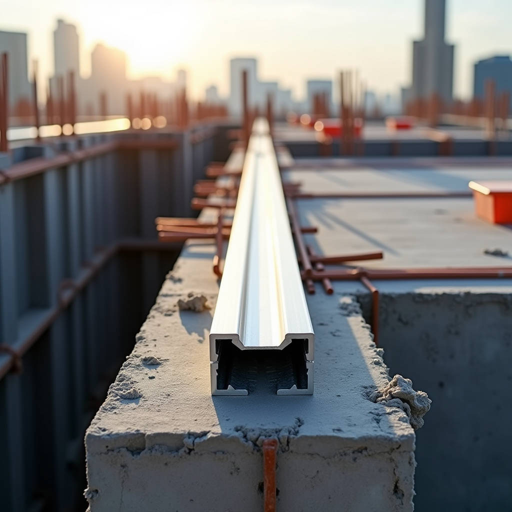
Every curtain wall project begins underground. Before the first aluminium panel is hoisted into place, a network of steel and aluminium components sits locked inside cured concrete, waiting to carry the weight of the facade. These are Aluminum Embedded Parts — the cast-in anchors, channels, and plates that bridge the structural skeleton to the exterior skin. A specification error here, a millimeter of misalignment, and the entire cladding system inherits a problem that no amount of shimming can fully correct. This article examines the engineering logic behind aluminium embedded parts in unitized curtain wall systems, the material grades that actually perform over a 50-year service life, and the procurement pitfalls that cost contractors weeks of remedial work. If you are specifying, sourcing, or installing solid aluminium cladding panels on a high-rise, the decisions made about embedded parts will determine whether the facade stands straight or drifts out of tolerance floor by floor.
The Engineering Function of Aluminum Embedded Parts in Curtain Wall Systems
An embedded part is not a bracket. It is the interface between two fundamentally different structural systems: the cast-in-place or precast concrete primary structure, and the lightweight aluminium framing that supports the cladding. In a unitized curtain wall, Aluminum Embedded Parts typically take the form of slotted cast-in channels, T-bolts, or anchor plates that are positioned on the formwork before the concrete pour. Once the concrete cures, these components provide a threaded or slotted connection point for the aluminium mullion brackets.
The load path is straightforward but unforgiving. Wind pressure hits the solid aluminium panel, transfers through the panel fixings into the vertical mullions, then through the bracket assembly into the embedded channel, and finally into the reinforced concrete slab edge. Each interface introduces a potential failure mode. The embedded part must resist pull-out forces, shear forces, and — critically in high-seismic zones — cyclic loading that can loosen a poorly specified anchor over time.
What distinguishes aluminium embedded parts from their carbon steel counterparts is the corrosion compatibility question. When a galvanized steel channel sits inside concrete and connects to an aluminium bracket, the galvanic potential between the two metals must be managed. Aluminium-to-aluminium connections eliminate this risk entirely, which is why many specifiers now mandate 6061-T6 or 6082-T6 aluminium embedded channels for projects within 5 kilometers of a coastline or in industrial zones with elevated atmospheric sulfur.
Material Grades That Survive a 50-Year Building Life
Not all aluminium alloys are suitable for embedment in concrete. The alkaline environment of curing concrete (pH typically 12-13) attacks unprotected aluminium aggressively during the first 72 hours after pouring. This is the critical window. Once the concrete has fully cured and dried, the corrosion rate drops significantly, but the initial chemical attack can compromise the load-bearing cross-section if the wrong alloy or coating is specified.
The industry has largely converged on two alloys for Aluminum Embedded Parts in facade applications:
- 6061-T6: Good strength-to-weight ratio, excellent extrudability for complex channel profiles, and widely available. Yield strength around 240 MPa. Suitable for most mid-rise and high-rise curtain wall applications where the embed depth is adequate.
- 6082-T6: Higher strength (yield around 260 MPa), slightly better corrosion resistance than 6061, and preferred in European projects under EN 1999-1-1. The manganese content in 6082 provides better grain structure after extrusion, which translates to more consistent mechanical properties along the length of a channel.
A common mistake is specifying 6063-T5 for embedded channels. While 6063 extrudes beautifully and anodizes well, its yield strength (around 145 MPa) is insufficient for the point loads concentrated at T-bolt connections. The bolt head can deform the channel lip under design wind loads, leading to loosening and eventual fatigue cracking. This failure mode has been documented in post-installation forensic reports on buildings in typhoon-prone regions.
For projects where aluminium embedment is not feasible — such as in highly aggressive soil conditions or where the structural engineer mandates steel — a 316L stainless steel cast-in channel with an isolating neoprene or EPDM gasket between the steel and aluminium bracket is the standard compromise. The gasket breaks the galvanic circuit. Without it, the aluminium bracket becomes the sacrificial anode and corrodes at an accelerated rate.
Cast-In Channels vs. Post-Installed Anchors: A Cost and Tolerance Comparison
The decision between cast-in aluminium channels and post-installed mechanical or chemical anchors is not purely a design choice. It affects the construction program, the achievable installation tolerances, and the total installed cost per connection point. The table below summarizes the trade-offs based on data from completed high-rise projects across Southeast Asia and the Middle East.
| Parameter | Aluminium Cast-In Channel | Post-Installed Mechanical Anchor | Post-Installed Chemical Anchor |
|---|---|---|---|
| Adjustment Range (3D) | ±25mm vertical, ±20mm lateral | ±5mm (slotted bracket only) | ±5mm (slotted bracket only) |
| Installation Speed | Cast with formwork; no drilling | Drilling required per anchor | Drilling + curing time (45-90 min) |
| Edge Distance Sensitivity | Low; channel distributes load | High; minimum 100mm from edge | Moderate; 80mm typical |
| Corrosion Risk (Coastal) | Low (aluminium-to-aluminium) | Moderate (galvanic couple) | Low if stainless stud used |
| Cost per Connection (USD) | $18–$32 | $12–$22 | $15–$28 |
| Quality Control | Surveyed before pour | Pull-out tested on-site | Pull-out tested; temperature-dependent |
| Seismic Performance | Good; continuous slot allows slip | Rigid; limited ductility | Moderate; depends on resin type |
The cost figures above are indicative for a 40-story project in Southeast Asia, based on 2024 contractor pricing. The cast-in channel appears more expensive per unit, but the total installed cost often favors it when the reduced surveying rework and faster bracket installation are factored in. A project with 2,000 connection points can save 8-12 working days on the facade installation program by eliminating the drilling and testing cycle required for post-installed anchors.
Tolerance Stack-Up: Why 3mm at the Embed Becomes 15mm at the Panel
The most expensive phone call a facade contractor can receive is the one telling them the embedded parts are out of position. In a unitized system, the tolerance chain starts at the concrete structure and amplifies through each connection. The cast-in channel is set on the formwork with a target position. The concrete pour can shift it. The bracket connects to the channel with some play. The mullion connects to the bracket. The panel clips to the mullion. Each joint adds its own tolerance.
A typical tolerance stack-up for a unitized curtain wall with Aluminum Embedded Parts looks like this:
- Embedded channel positional deviation after pour: ±5mm
- T-bolt positioning within channel slot: ±2mm
- Bracket fabrication tolerance: ±1.5mm
- Mullion fabrication tolerance: ±1mm
- Panel clip adjustment range: ±3mm
At the panel face, these accumulate to a potential deviation of ±12.5mm from the theoretical plane. For a 3-meter solid aluminium panel with a 20mm open joint, that deviation is visible. The joint width varies, shadow lines shift, and the architect's intended visual rhythm breaks down.
The solution is not to tighten every tolerance — that becomes prohibitively expensive. The smarter approach is to design the bracket connection with sufficient 3-axis adjustability to absorb the upstream deviations. A well-designed aluminium bracket system connected to a cast-in channel should provide at least ±20mm of adjustment in the vertical and horizontal planes, and ±15mm in the in-out direction. This is why slotted channels, not fixed anchor plates, dominate high-rise unitized facade specifications.
Coastal and Industrial Corrosion: The Coating Question
Aluminium embedded parts in concrete benefit from the passive alkaline environment once the concrete has cured, but the exposed portion — the channel mouth and the T-bolt connection — remains vulnerable. In coastal environments with chloride deposition rates exceeding 60 mg/m²/day (common within 500 meters of breaking surf), even 6061-T6 aluminium can develop pitting corrosion if left unprotected.
The protective strategy for aluminium embedded channels typically follows a two-tier approach:
- Mill finish with anodizing: A 15-20 micron anodic layer (AA-M10C22A31 per AAMA 611) provides a durable barrier. This is adequate for inland and urban environments. The anodized surface also improves the friction characteristics of the T-bolt connection, reducing the risk of loosening under vibration.
- Polyester or epoxy powder coating: For coastal and industrial environments, a 60-80 micron powder coat applied to the exposed face of the channel provides additional protection. The coating must be masked from the load-bearing surfaces to avoid compromising the bolt clamping force through creep of the polymer layer under sustained load.
A field study conducted on a 15-year-old building in Jeddah, where aluminium embedded channels were specified with 20-micron anodizing, found no measurable loss of cross-section on the embedded portion but minor pitting (0.1-0.3mm depth) on the exposed channel mouth. The structural capacity remained above 95% of the original design value. This aligns with the expectation that properly specified aluminium embedded parts can meet a 50-year service life without replacement, provided the environmental exposure is correctly assessed at the design stage.
For projects where the embedded parts must interface with solid aluminium cladding panels finished in PVDF (polyvinylidene fluoride) coatings — typically a 3-coat system with a total dry film thickness of 35-40 microns per AAMA 2605 — the galvanic compatibility between the embedded channel and the panel itself is not a concern, as the two components are separated by the mullion and bracket assembly. However, the bracket material must match the embedded channel material to avoid creating a galvanic cell at the bolted connection.
Procurement Pitfalls That Delay Projects
Sourcing Aluminum Embedded Parts for a large curtain wall project involves a supply chain that is easy to underestimate. The embedded parts are needed before the facade contractor typically mobilizes on site. They must be on the formwork when the concrete is poured, which means they are required during the structural frame construction phase — often 6-12 months before the cladding panels arrive.
The procurement timeline for a typical high-rise project breaks down as follows:
- Engineering and shop drawings: 4-6 weeks. The embedded part layout must be coordinated with the structural engineer's rebar drawings. A clash between an embedded channel and a congested reinforcement cage can force a redesign.
- Extrusion die fabrication: 3-4 weeks for custom channel profiles. Standard profiles are available from stock, but most projects require some customization for the slot geometry or the anchor stud spacing.
- Production and fabrication: 6-8 weeks for a typical order of 3,000-5,000 linear meters of channel with welded anchor studs.
- Surface treatment: 1-2 weeks for anodizing or powder coating.
- Shipping: 4-6 weeks from factory to site (Asia to Middle East or Europe).
A total lead time of 16-22 weeks is realistic. Contractors who leave the embedded part order until after the main contract award often find themselves delaying the concrete pour or, worse, switching to post-installed anchors as a recovery measure — incurring the cost and program penalties discussed earlier.
Fabricators such as Futeng® that maintain dedicated extrusion lines for architectural aluminium profiles can compress this timeline by running standard channel profiles against forecast demand rather than against specific orders. This approach — maintaining buffer stock of the most common 6061-T6 channel sections — can reduce lead time to 8-10 weeks for projects that can adapt their design to a standard profile.
Quality Verification: What to Check Before the Concrete Pour
The window for quality control on embedded parts is narrow. Once the concrete is poured, access to the part is limited to the exposed face. Everything else is locked in. The following checks should be completed and documented before the pour:
- Positional survey: Each embedded channel or anchor plate must be surveyed against the setting-out grid. The tolerance for position should be ±3mm in plan and ±5mm in elevation. A total station survey with a digital record is standard practice on projects above 20 stories.
- Fixing integrity: The channel must be securely fixed to the formwork or rebar cage to prevent flotation or displacement during concrete placement. Wire ties, magnetic holders, or bolted connections to the formwork are all acceptable, provided they resist the buoyancy forces of the concrete.
- Channel mouth protection: The slot must be filled with a removable foam or plastic strip to prevent concrete ingress. Concrete slurry inside the channel slot renders the T-bolt connection unusable. Removing hardened concrete from an aluminium channel slot is time-consuming and risks damaging the channel lip.
- Material certification: Mill certificates for the aluminium extrusion should confirm the alloy grade (6061-T6 or 6082-T6), the mechanical properties (yield strength, ultimate tensile strength, elongation), and the chemical composition. For projects requiring compliance with ISO 9001 quality management systems, full traceability from billet to finished channel is expected.
- Anchor stud weld inspection: If the channel incorporates welded anchor studs (typically M12 or M16 stainless steel or aluminium studs), the weld quality must be verified. A sample pull-out test on a sacrificial channel from the same production batch provides confidence that the weld strength exceeds the design load.
On a 50-story tower with 80 embedded channels per floor, the total number of channels is 4,000. Surveying each one is a significant task, but the cost of rework — drilling out misaligned channels and installing post-installed anchors — typically runs 3-5 times the cost of the original embedded part per connection. The economics of thorough pre-pour QC are unambiguous.
Solid Aluminium Panels and the Embedded Connection: Why Panel Thickness Matters
The solid aluminium cladding panels that ultimately hang from these embedded connections carry their own set of requirements. A 2.5mm or 3.0mm thick solid aluminium panel (alloy 1100-H14 or 3003-H14) with a PVDF coating weighs approximately 7-8.5 kg/m². A typical unitized panel measuring 1.5m wide by 3.6m tall covers 5.4 m² and weighs around 40-46 kg. Add the aluminium sub-frame, and the total weight per unit approaches 60-70 kg.
This weight, multiplied across thousands of units, must be transferred to the structure through the embedded parts. The design load per connection point is typically calculated based on the tributary area of the panel and the local wind load per ASCE 7 or the relevant regional code. For a high-rise in a typhoon zone with a design wind pressure of 3.5 kPa, a single connection point might need to resist 8-12 kN of tensile force and 4-6 kN of shear force.
An aluminium 6061-T6 cast-in channel with a 30mm x 20mm cross-section and a 2.5mm wall thickness, paired with an M12 T-bolt, can typically handle a tensile load of 15-20 kN per bolt when the load is applied perpendicular to the channel axis. This provides a comfortable safety factor of 1.5-2.0 against the design load. However, if the load is applied at an angle — as happens when the bracket is used to correct for an out-of-position embed — the capacity drops. A 15-degree load angle can reduce the tensile capacity by 10-15%. This reduction must be accounted for in the connection design, particularly for the top-floor connections where wind suction forces are highest.
Integration with Building Information Modeling
The coordination of Aluminum Embedded Parts with the structural frame has been transformed by BIM workflows. In a typical Level 2 BIM project, the embedded parts are modeled as individual families within the structural model. The facade contractor's bracket and mullion model is overlaid, and clash detection identifies conflicts between the bracket position and the rebar layout.
The value of this coordination is highest at the slab edge, where the density of reinforcement is greatest. A clash between an embedded channel anchor stud and a 25mm diameter rebar can be resolved in the model by shifting the channel 50mm along the slab edge. Resolving the same clash on site, after the rebar is tied, requires cutting and re-tying the reinforcement — a slower and more expensive process.
For projects pursuing ISO 19650 compliance, the embedded parts should be classified under the Uniclass 2015 system as Pr_20_85_08 (Cast-in anchorages and fixings) and linked to the corresponding COBie data drops for asset information requirements. This level of data structuring supports the eventual handover of the digital twin to the building operator, who may need to reference the embedded part locations for future facade maintenance or replacement.
Common Failure Modes and How to Avoid Them
Engineering failures involving embedded parts in curtain wall systems are rarely catastrophic. They are more often chronic: progressive loosening, water ingress through the connection, or accelerated corrosion that reduces the service life of the facade. The most frequently observed failure modes include:
- Concrete breakout: The embed is too close to the slab edge, and the concrete cone fails under tensile load. The minimum edge distance for an aluminium cast-in channel is typically 100mm from the slab edge, measured to the centerline of the channel. This increases to 150mm for corner conditions where the concrete is subject to biaxial stress.
- Channel lip deformation: The T-bolt is overtightened or the channel material is too soft (e.g., 6063-T5 instead of 6061-T6). The lip deforms plastically, the clamping force is lost, and the bolt can slide along the slot under wind-induced vibration.
- Galvanic corrosion at the bolt interface: A stainless steel T-bolt in an aluminium channel creates a galvanic couple. In the presence of moisture (from condensation or rain ingress through the facade joint), the aluminium corrodes preferentially. The solution is to specify aluminium T-bolts (6061-T6) for aluminium channels, or to use a stainless steel bolt with a durable isolating coating such as Xylan or Geomet.
- Water ingress through the embed: If the embedded channel penetrates the waterproofing membrane at the slab edge, water can track along the channel into the interior. A continuous sealant bead around the channel mouth, applied before the bracket is installed, is the standard defense.
Each of these failure modes is preventable through specification discipline. The cost of prevention — specifying the correct alloy, maintaining edge distances, and applying protective coatings — is a fraction of the cost of remediation after the facade is installed.
Making the Right Specification Decision
The specification of Aluminum Embedded Parts for a solid aluminium cladding facade is a decision that sits at the intersection of structural engineering, corrosion science, and construction logistics. The right choice depends on the project's specific conditions: the distance from the coast, the seismic zone, the concrete mix design, the facade system type, and the construction program.
For most high-rise unitized curtain wall projects with solid aluminium panels, a 6061-T6 or 6082-T6 aluminium cast-in channel with anodized protection, paired with matching aluminium T-bolts, represents the most robust and corrosion-compatible solution. The higher unit cost relative to galvanized steel channels is offset by the elimination of galvanic corrosion risk and the reduction in long-term maintenance liability.
For low-rise projects or those with generous construction tolerances, post-installed anchors may be adequate. But the decision should be made consciously, with an understanding of the tolerance implications and the additional on-site quality control burden that post-installed systems require.
The embedded part is the one component of the facade that cannot be replaced without demolishing concrete. Every other component — panels, gaskets, brackets, bolts — can be accessed and swapped. That permanence demands a higher standard of care in material selection, quality control, and installation accuracy. The projects that get this right are the ones where the facade contractor, structural engineer, and concrete subcontractor coordinate their work from the earliest stages of the program. The ones that do not are the projects where the cladding panels never quite align, and the building carries that evidence for its entire life.
Embedded parts are the foundation of facade engineering. The panel alignment, the joint consistency, and the long-term structural integrity of the entire cladding system trace back to what was cast into the concrete months before the first panel arrived on site.