Aluminum Adjustable Bracket Engineering for Solid Aluminium Cladding Facade Systems
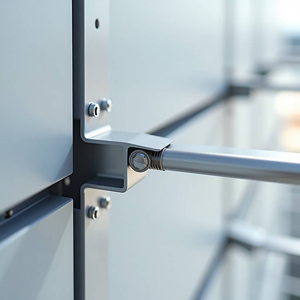
When a cladding contractor on a high-rise in Dubai or a mixed-use tower in Singapore calls out substandard installation, the root cause rarely traces back to the panel itself. More often, the failure lives in the connection: a bracket that couldn't hold tolerance, a fixed anchor that fought the building's natural movement, or a galvanic pairing that corroded within three monsoon seasons. The Aluminum Adjustable Bracket has quietly become the most over-engineered yet under-discussed component in modern rainscreen and unitized curtain wall systems. This piece strips away the catalog language and examines what actually matters when specifying these brackets for solid aluminium cladding panels — from differential thermal movement and slot geometry to alloy selection, load path logic, and the procurement traps that cost projects six figures in remedial work.
Why the Bracket Defines the Cladding System More Than the Panel
Solid aluminium cladding panels — 2.5 mm or 3.0 mm thick, PVDF-coated, fabricated to millimeter-level precision — arrive on site as rigid, dimensionally stable elements. The panel itself is predictable. The building is not. Concrete frames creep. Steel subframes expand. Wind loads shift from positive pressure to suction across a single elevation. The Aluminum Adjustable Bracket sits at the intersection of these competing forces, and its job is deceptively simple: maintain panel position while absorbing movement in three axes without transferring stress into the panel skin.
Most specification failures happen because the bracket gets treated as a commodity. A procurement team sources a generic slotted angle from a catalog, checks the load rating on a static table, and moves on. The problem is that a static load rating tells you nothing about cyclic performance, nothing about how the slot geometry interacts with bolt torque under vibration, and nothing about what happens when the aluminium bracket is bolted to a galvanized steel substructure in a coastal environment.
What separates a bracket that works for 25 years from one that triggers a facade remediation contract is a set of design decisions made long before the first anchor is drilled. Those decisions live in four technical domains: alloy selection, slot design, surface treatment, and load path continuity.
Alloy Selection: 6061-T6 vs. 6063-T5 and Why It Matters for Adjustable Brackets
The aluminium extrusion industry defaults to 6063-T5 for most architectural profiles. It extrudes easily, takes anodizing well, and costs less per kilogram. For an Aluminum Adjustable Bracket that carries dead load, wind load, and cyclic thermal stress, 6063-T5 can be the wrong choice. The tensile strength of 6063-T5 sits around 145 MPa, while 6061-T6 delivers roughly 290 MPa — nearly double the ultimate tensile capacity. When a bracket arm extends 150 mm from the anchor point and carries a 3.0 mm solid aluminium panel weighing 8.1 kg/m² plus wind suction, the bending moment at the connection demands material that doesn't creep under sustained load.
Creep is the silent failure mode. Aluminium alloys under constant stress at temperatures above 100°C can deform permanently over time. Facade cavities in Middle Eastern and Southeast Asian markets routinely hit 85°C to 95°C behind dark-colored panels. A 6063-T5 bracket with a thin cross-section and a poorly radiused slot corner can lose clamp force gradually, leading to panel slippage that manifests as uneven joint lines three years after handover.
6061-T6 extrusions cost more and require tighter die maintenance, but for any project exceeding 15 stories or located in a high-wind zone, the alloy upgrade is cheap insurance. The specifier should also verify that the bracket manufacturer provides mill test certificates traceable to the heat number, not just a generic statement of compliance. Futeng® and other manufacturers serving the Southeast Asian and Middle Eastern markets have moved toward 6061-T6 as a standard offering for adjustable bracket systems paired with solid aluminium cladding panels, precisely because the warranty exposure on 6063-T5 brackets has become untenable.
Slot Geometry: The 3 mm Difference That Determines Adjustability
An Aluminum Adjustable Bracket earns its name from the slot. The slot allows the installer to position the panel in the X, Y, or Z axis — depending on bracket orientation — after the anchor is fixed. But not all slots are equal. The three parameters that control real-world adjustability are slot width tolerance, slot length, and edge distance from the slot end to the bracket edge.
Slot width tolerance is where site conditions collide with factory specifications. A bracket designed for an M8 bolt typically specifies a 9 mm wide slot — 1 mm of clearance on the bolt diameter. That clearance works on paper. On site, the subframe may be welded with a ±3 mm positional tolerance. The bracket needs to shift laterally to absorb that deviation, but if the slot width is too tight, the bolt binds before the bracket reaches the correct position. If the slot is too wide — say 11 mm for an M8 bolt — the bolt head or washer can pull through under tension, especially when the bracket is loaded in shear during wind events.
The optimal slot width for an M8 fastener in a 6061-T6 bracket is 9.5 mm, with the slot edges chamfered at 0.5 mm to prevent stress risers. The slot length should provide at least 25 mm of continuous adjustment range, and the slot ends should be radiused, not square-cut. A square-ended slot concentrates stress at the corners and becomes a crack initiation point under cyclic loading. This detail alone separates brackets that pass AAMA 501.4 dynamic testing from those that fracture during the water infiltration sequence.
Edge Distance and Tear-Out Failure
The distance from the center of the slot to the edge of the bracket in the direction of load is the edge distance. For an M8 bolt in 6061-T6 aluminium, the minimum edge distance should be 1.5 times the bolt diameter — 12 mm — but this is a minimum, not a target. In practice, 16 mm to 20 mm provides a safer margin, particularly when the bracket is slotted and the bolt can be positioned anywhere along the slot length. If the bolt sits at the extreme end of the slot, the effective edge distance shrinks, and the risk of tear-out failure under shear increases sharply.
Contractors who have dealt with tear-out on site know the pattern: the bracket doesn't snap; the bolt simply pulls through the slot end, leaving an elongated hole and a panel that's now hanging on its neighbors. The fix requires scaffolding, panel removal, and bracket replacement — a cost that can exceed $200 per bracket when access and downtime are factored in.
Galvanic Corrosion: The Hidden Cost of Mixing Metals
An aluminium bracket bolted to a steel substructure creates a galvanic cell. Aluminium is anodic to steel; in the presence of an electrolyte — rainwater, condensation, coastal salt spray — the aluminium sacrifices itself. The corrosion rate depends on the surface area ratio, the conductivity of the electrolyte, and the effectiveness of the isolation barrier.
The standard mitigation is a physical barrier: a nylon or EPDM isolation pad between the bracket and the steel, plus a nylon washer under the bolt head. But these barriers degrade. EPDM hardens and cracks after 15 years of thermal cycling. Nylon absorbs moisture and swells, changing the clamp load on the bolt. The more robust approach combines isolation with coating: the steel substructure should be hot-dip galvanized to ASTM A123 or ASTM A153, and the aluminium bracket should be anodized to at least AA-M12C22A31 (Class I architectural anodizing) or, better, supplied with a 60-micron minimum PVDF coating that matches the panel finish.
Anodizing alone is not sufficient for brackets in marine environments. Anodized aluminium still pits when exposed to chloride ions. A PVDF-coated bracket, using the same resin system as the cladding panel — typically a 70% PVDF formulation with inorganic pigments — provides a matched service life. The bracket and panel weather together, and the building owner doesn't face a scenario where the panels look pristine but the brackets have corroded to the point of structural compromise.
| Corrosion Protection Method | Typical Service Life (Coastal) | Relative Cost | Compatibility with Solid Aluminium Panels |
|---|---|---|---|
| Mill Finish (No Protection) | 2-5 years | Base | Not recommended |
| Clear Anodizing (AA-M12C22A31) | 10-15 years | +15% | Acceptable for inland |
| PVDF Coating (60-80 microns) | 25+ years | +30% | Optimal — matched system |
| Anodizing + EPDM Isolation | 15-20 years | +20% | Good for urban environments |
| PVDF + Stainless Steel Hardware | 30+ years | +40% | Best practice for marine/coastal |
Thermal Movement: Why Adjustable Brackets Are Not Optional
Aluminium expands at roughly 2.4 mm per linear meter per 100°C temperature change. A 4-meter-long solid aluminium cladding panel subjected to a 70°C temperature swing — from a winter night low of -10°C to a summer afternoon cavity temperature of 60°C — will grow by approximately 6.7 mm in length. If the panel is rigidly fixed at both ends, that 6.7 mm of expansion has nowhere to go. The panel buckles, the fasteners loosen, or the bracket itself yields.
The Aluminum Adjustable Bracket solves this by allowing one end of the panel to float. The typical arrangement uses a fixed bracket at one end of the panel — often the top — and a sliding bracket at the opposite end. The sliding bracket's slot is oriented parallel to the direction of thermal expansion, and the bolt is torqued to a value that permits movement under thermal load but resists movement under wind load. This torque specification is critical: too tight, and the panel can't expand; too loose, and the panel rattles under wind buffeting.
For a 3.0 mm solid aluminium panel with a PVDF finish, the recommended torque on an M8 stainless steel bolt in a slotted bracket is 18-22 Nm, applied with a calibrated torque wrench. This range provides sufficient clamp force to resist wind-induced vibration while allowing the panel to slide under thermal expansion forces. Installers should be trained to verify torque with a calibrated wrench, not an impact driver, and the torque values should be recorded on a quality control sheet for each elevation.
Load Path: From Panel Face to Building Structure
The load path for a solid aluminium cladding panel travels through four connection points: the panel skin, the panel stiffener or rail, the Aluminum Adjustable Bracket, and the building substructure. Each interface introduces a potential failure point. The most common failure is not the bracket itself but the connection between the bracket and the panel rail — typically a rivet or a self-tapping screw that shears under wind suction.
Wind suction is the dominant load on a cladding panel. Positive pressure pushes the panel against the building; suction pulls it away. The suction load on a panel at the corner of a high-rise can be 2.5 to 3.0 times the positive pressure on the building face, per ASCE 7 wind load provisions. A bracket that comfortably handles positive pressure may fail under suction because the load direction reverses and the fasteners are now in tension rather than shear.
The bracket-to-rail connection should use stainless steel blind rivets with a mandrel retention system, not standard open-end rivets. The mandrel in a blind rivet with retention stays in place after setting, providing shear resistance across the full cross-section of the rivet body. An open-end rivet loses its mandrel after setting, leaving a hollow body with roughly 40% less shear capacity. For a 3.0 mm panel in a high-wind zone, 6.4 mm diameter stainless steel blind rivets with a grip range matched to the combined thickness of the bracket and rail are the minimum acceptable standard.
Procurement Traps: What the Catalog Doesn't Tell You
Purchasing an Aluminum Adjustable Bracket from a catalog or an online marketplace is straightforward. Purchasing 8,000 brackets for a 40-story tower and ensuring every single one performs identically is a different discipline entirely. The traps that catch procurement managers fall into three categories: batch consistency, documentation, and logistics.
Batch consistency means that bracket number 1 and bracket number 8,000 came from the same extrusion die, the same anodizing tank, and the same quality control process. Aluminium extrusion dies wear over time. A die that produces a 9.5 mm slot width on day one may produce a 9.8 mm slot width after 30,000 cycles. If the procurement is split across two production batches, the second batch may have slot dimensions that drift outside the acceptable tolerance. The fix is to specify that all brackets for a given project must come from a single production batch, and that the manufacturer must provide dimensional inspection reports for a statistically valid sample per ISO 2859-1 sampling plans.
Documentation is the second trap. A bracket supplier who ships product with a one-page invoice and no test reports is transferring risk to the contractor. The minimum documentation package should include mill test certificates for the aluminium extrusion, coating thickness measurements, salt spray test results per ASTM B117 for the surface treatment, and a certificate of conformance stating that the brackets meet the project specification. For projects in the Middle East, Dubai Civil Defense and other authorities may require additional fire performance documentation, even for non-combustible aluminium components.
Logistics is the third trap. Aluminium brackets are bulky relative to their weight. A container of brackets ships by volume, not weight, and freight costs can exceed the product cost on long-haul routes. Smart procurement consolidates bracket shipments with panel shipments from the same factory, reducing per-unit freight by 30% to 40%. Futeng® and other integrated manufacturers that produce both solid aluminium panels and adjustable brackets under one roof offer a logistical advantage here: the brackets are packed in the same container as the panels, arriving on site together and eliminating the risk of a bracket delay holding up the entire cladding installation.
Site Handling and Installation Realities
The best-designed bracket fails if it's installed incorrectly. The two most common installation errors are over-torquing the anchor bolt and using the bracket slot as a pry point to force panel alignment. Over-torquing an M8 stainless steel bolt into an aluminium bracket can strip the threads or deform the slot, reducing the bracket's adjustability to zero. The installer, frustrated that the panel won't align, then uses a crowbar against the bracket to force the panel into position, bending the bracket arm and introducing residual stress that shortens fatigue life.
The solution is not a better bracket design; it's a better installation protocol. The protocol should require that all brackets be installed loosely — bolts finger-tight — until the entire elevation is hung. Only after the panels are aligned and the joint widths are verified should the bolts be torqued to specification. This sequence allows the brackets to find their natural position within the slot range, absorbing the accumulated tolerances of the substructure without forcing any single bracket beyond its design limits.
Testing Standards That Apply to Adjustable Brackets
An Aluminum Adjustable Bracket used in a rainscreen or curtain wall system should be tested as part of the overall assembly, not in isolation. The relevant standards include ASTM E283 for air leakage, ASTM E331 for water penetration under static pressure, and AAMA 501.4 for dynamic water penetration with cyclic loading. The bracket's contribution to system performance is indirect but critical: a bracket that allows excessive panel movement under wind load will open the sealant joints and create air and water leakage paths.
For seismic zones, the bracket must also accommodate inter-story drift without losing panel support. The acceptance criteria in AAMA 501.6 for seismic drift testing require that the panel remain attached to the building and not create a falling hazard after the drift cycle. Adjustable brackets with slots oriented to permit in-plane movement are essential for meeting this requirement. Fixed brackets, by contrast, transfer drift forces directly into the panel, risking fastener shear or panel buckling.
When to Move Beyond the Standard Catalog Bracket
Standard adjustable brackets work for 80% of solid aluminium cladding applications: flat panels, moderate wind zones, buildings under 20 stories. The remaining 20% require custom engineering. The triggers for custom bracket design include panel weights exceeding 12 kg/m², panel dimensions exceeding 1.5 meters in any direction, wind suction pressures above 3.0 kPa, and buildings in Seismic Design Category D or higher.
Custom brackets typically involve thicker sections — 5 mm or 6 mm instead of the standard 3 mm or 4 mm — longer slots for greater adjustment range, and additional stiffening ribs to resist buckling under compression. The engineering cost for custom brackets adds roughly $2,000 to $5,000 to a project, but this is a fraction of the cost of a single panel replacement after a bracket failure. The decision to go custom should be made during the design development phase, not during shop drawing review, because the bracket geometry affects the panel rail layout and the anchor spacing on the substructure.
The Aluminum Adjustable Bracket is not a commodity. It is a load-bearing, movement-accommodating, corrosion-resisting engineered component that determines whether a solid aluminium cladding system performs for 30 years or fails in five. The specifier who understands alloy grades, slot geometry, galvanic isolation, and thermal movement will write a specification that protects the building owner from the costs of facade remediation. The specifier who treats the bracket as an afterthought will eventually explain to a client why the panel joints are uneven, the sealant is cracked, and the brackets need replacement at year seven.
Specify the bracket with the same rigor as the panel. The panel is what the building owner sees. The bracket is what the building owner pays for when it fails.